Impulsion Line Installation 2D Section Layout With Pipe Crossing
Ratings & Reviews
Be the first to share your experience with this product. Your review helps others make better decisions!
Description
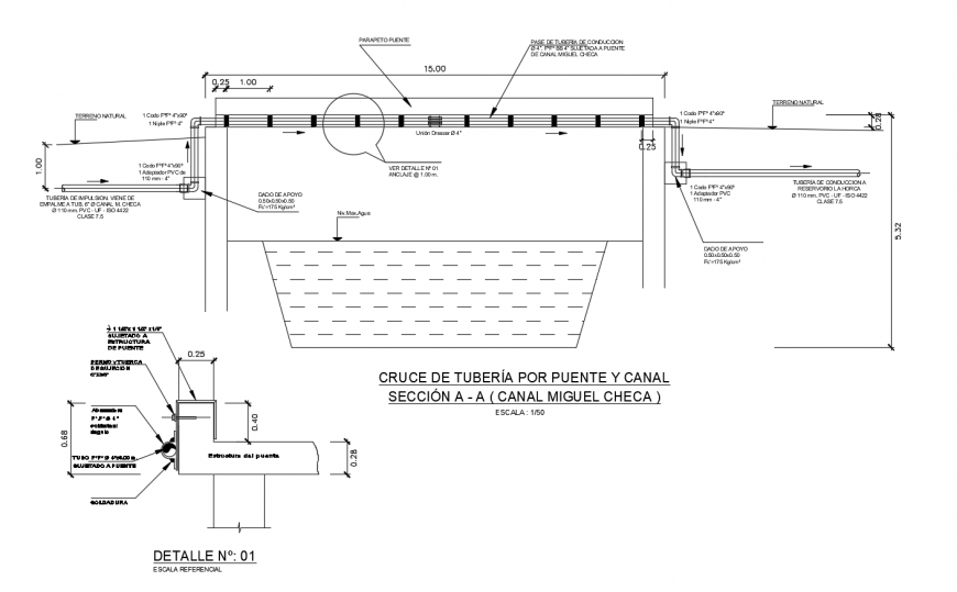
This AutoCAD DWG drawing presents detailed impulsion line installation 2D information prepared for infrastructure and utility planning projects. The drawing includes a clear sectional view of a pipe crossing over a bridge and canal, showing accurate alignment and installation methodology. Pipe positioning is illustrated with proper support arrangement, anchoring points, and level coordination to ensure safe and stable installation. Sectional details of the bridge structure are included, explaining how the impulsion line is supported and fixed without disturbing structural integrity. Dimensions are clearly marked to define pipe diameter, spacing, support offsets, and installation heights, supporting precise construction and execution.
The impulsion line installation drawing also explains canal crossing details with a clear representation of pipe alignment, clearance levels, and structural interfaces. Installation components, fixing details, and sectional references help engineers understand load transfer and maintenance accessibility. The drawing is drafted to scale in AutoCAD DWG format, maintaining the technical accuracy and clarity required for infrastructure documentation. This 2D impulsion line detail drawing is suitable for civil engineers, infrastructure planners, utility consultants, and contractors involved in water supply, pumping systems, and pipeline crossing projects, providing a reliable reference for pipe installation over bridges and canals with accurate dimensional control.
Tags
Uploaded by:
Eiz
Luna
Ratings & Reviews
Be the first to share your experience with this product. Your review helps others make better decisions!