Water Machinery System 2D Layout With Mechanical Assembly Details
Tags
Ratings & Reviews
Be the first to share your experience with this product. Your review helps others make better decisions!
Description
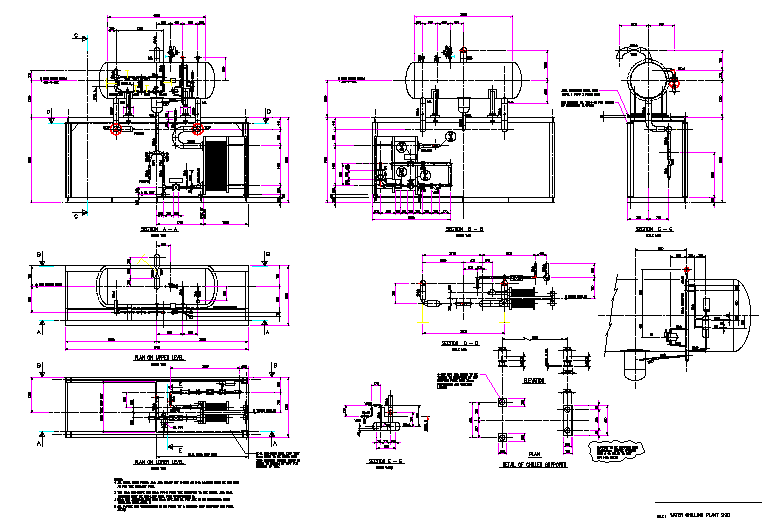
This AutoCAD DWG drawing presents a detailed water machinery system design prepared for mechanical and utility planning applications. The drawing includes comprehensive 2D layouts of water machinery assemblies with clearly defined component positioning and dimensional coordination. Multiple views such as plan views, sectional views, and side elevations are provided to explain internal arrangement, equipment alignment, and installation relationships. Mechanical elements such as tanks, pumps, pipelines, valves, connectors, and support frames are illustrated with accurate dimensions to support precise fabrication and installation. Connection points, flow direction indicators, and mounting references are clearly marked to ensure correct mechanical and hydraulic coordination.
The water machinery drawing also includes detailed sectional information that explains internal clearances, equipment spacing, and structural support requirements. Dimensional annotations support alignment accuracy and maintenance access planning. Notes and reference details help in understanding assembly sequence and system integration. Drafted to scale in AutoCAD DWG format, this drawing maintains professional drafting standards and technical clarity. The water machinery 2D design file is suitable for mechanical engineers, civil engineers, utility planners, contractors, and CAD professionals involved in water supply systems, pumping installations, and infrastructure projects requiring reliable machinery layout and detailed mechanical documentation.

Uploaded by:
Jafania Waxy
Tags
Ratings & Reviews
Be the first to share your experience with this product. Your review helps others make better decisions!