Water Line Design 2D Layout With Pipeline and Chamber Details
Tags
Ratings & Reviews
Be the first to share your experience with this product. Your review helps others make better decisions!
Description
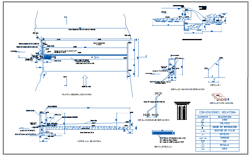
This AutoCAD DWG drawing presents a detailed water line design prepared in 2D view for utility and infrastructure planning. The drawing includes a complete general layout of the water pipeline showing alignment, flow direction, and connection points with accurate dimensional references. Sectional views are provided to explain pipe installation depth, bedding arrangement, and relation with surrounding ground levels. Chamber and derivation details are included, illustrating valve placement, access points, and maintenance provisions within the water supply network. Detailed drawings of pipe joints, transitions, and support elements help in understanding installation methodology and system continuity. Clear annotations, levels, and directional arrows support proper execution and flow control understanding.
The water line design drawing also includes specific detail views such as derivation chamber, valve box, cover details, and structural sections required for field installation. Standard symbols and conventions are provided to identify elements like valves, flow direction, pipes, and water connection points. All drawings are drafted to scale in AutoCAD DWG format, ensuring technical accuracy and construction readiness. This water line 2D drawing is suitable for civil engineers, utility planners, contractors, and infrastructure designers involved in water supply projects, offering clear pipeline layout, chamber detailing, and dimensional coordination for planning, approval, and execution.

Uploaded by:
Harriet Burrows
Tags
Ratings & Reviews
Be the first to share your experience with this product. Your review helps others make better decisions!