Machinery Designs with Detailed Assembly and Part Dimensions
Tags
Ratings & Reviews
Be the first to share your experience with this product. Your review helps others make better decisions!
Description
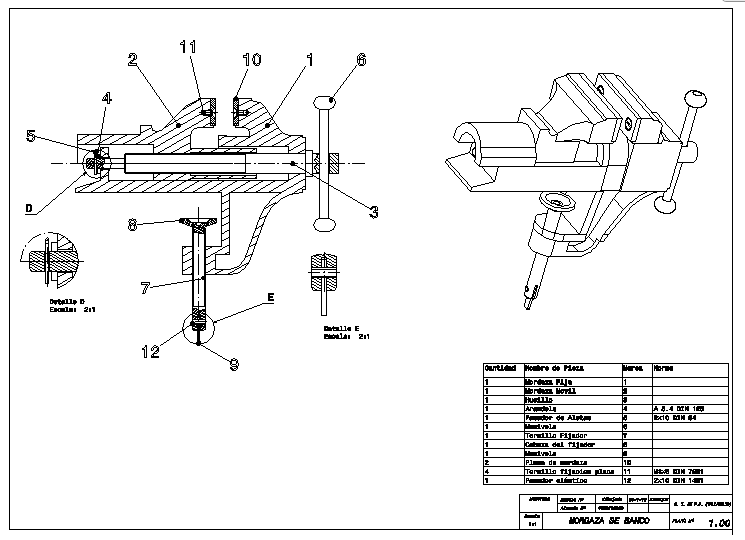
This Machinery Design AutoCAD drawing presents a complete technical representation of a mechanical bench vise-style assembly prepared with professional drafting standards. The drawing includes a detailed sectional view, an isometric view, and individual component identification with numbered callouts for accurate understanding of each part. Clear dimensions are provided for the main body, jaws, screw rod, handle, base clamp, and internal moving elements to support precise fabrication and installation. The file illustrates material thickness, assembly alignment, fastening positions, and working clearances required for workshop-level manufacturing. This drawing is suitable for mechanical detailing, machine shop reference, and technical education use. It helps architects, civil engineers, designers, and builders understand mechanical component coordination, load-bearing behavior, and functional movement within compact machinery units. The layout is clean and readable, making it useful for AutoCAD-based detailing, modification, and integration into larger mechanical or industrial projects.

Uploaded by:
Jafania Waxy
Tags
Ratings & Reviews
Be the first to share your experience with this product. Your review helps others make better decisions!