Aluminium Sliding Door Detail Drawing With Track Section Design
Tags
Ratings & Reviews
Be the first to share your experience with this product. Your review helps others make better decisions!
Description
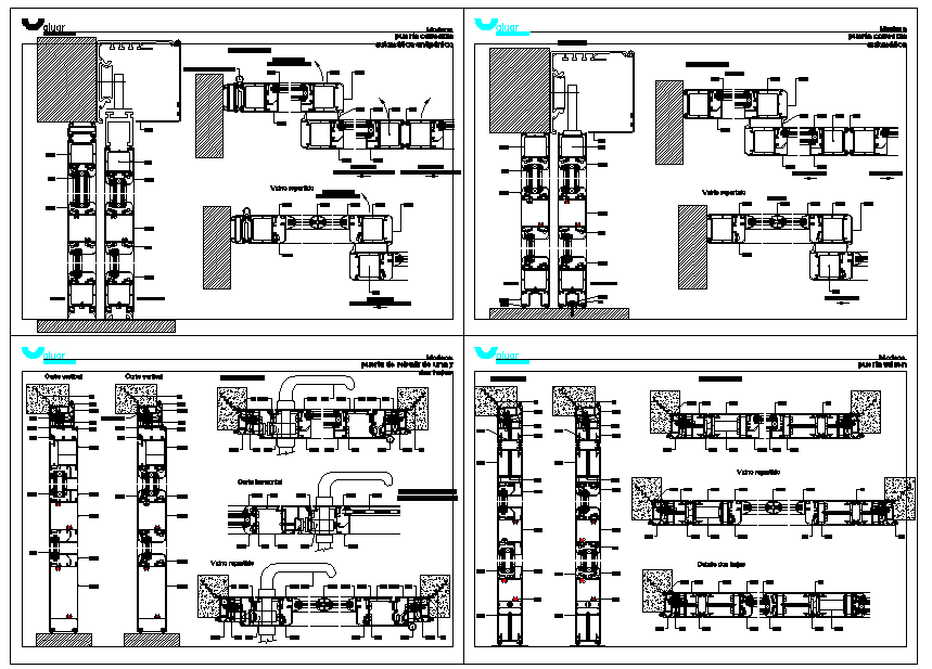
The aluminium sliding door detail drawing presents a clear and professional construction layout showing the complete door system in sectional and elevation views. This AutoCAD drawing illustrates the aluminium sliding door frame, shutter profile, track alignment, roller positioning, and sliding door section with precise mm-scale detailing. The drawing explains how the aluminium sections are fixed parallel to the wall, highlighting the movement path, clear opening, and structural coordination required for residential and commercial applications. Key elements such as top and bottom tracks, glass panel placement, frame depth, and fixing points are clearly represented to support accurate execution on site.
This aluminium sliding door detail drawing is ideal for architects, civil engineers, interior designers, and builders who require a reliable sliding door detail for planning and construction documentation. The aluminium door drawing supports coordination with wall finishes, floor levels, and ceiling junctions while maintaining smooth horizontal movement. The sliding door detail also helps in understanding load transfer, track thickness, and installation tolerance in mm measurements. Provided as an AutoCAD DWG file, this drawing is suitable for professional use in AutoCAD, 3d Max, Revit, and SketchUp-based workflows, making it a valuable reference for precise aluminium sliding door design and detailing.

Uploaded by:
Harriet Burrows
Tags
Ratings & Reviews
Be the first to share your experience with this product. Your review helps others make better decisions!