Detail of Pipe Main Hole Construction Drawing With Manhole Section
Tags
Ratings & Reviews
Be the first to share your experience with this product. Your review helps others make better decisions!
Description
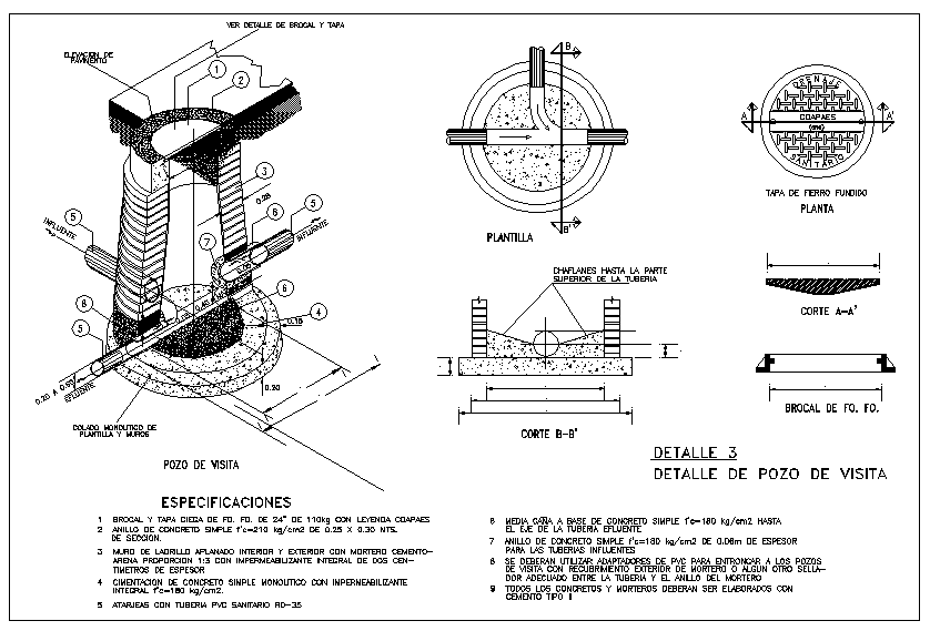
This detail of pipe main hole construction drawing presents a complete technical layout of a pipe manhole system shown through plan, section, and exploded views. The AutoCAD drawing illustrates the manhole chamber, pipe inlet and outlet connections, base slab, brick masonry walls, internal plaster finish, and cast iron cover with accurate millimeter measurements. Details include channel formation inside the manhole, benching slope toward the pipe, pipe alignment through the wall, and sealing treatment around penetrations. Dimensional references clearly define manhole diameter, wall thickness, base width, and cover positioning for proper installation.
The pipe main hole detail drawing is suitable for architects, civil engineers, infrastructure planners, and builders involved in drainage and utility projects. Sectional views explain load transfer, pipe continuity, and access cover placement to support maintenance requirements. The drawing supports correct coordination between underground pipelines, manhole depth, and surface level alignment using mm scale dimensions. Construction notes and material specifications help ensure durability and accurate execution on site. This AutoCAD DWG file can be directly used in AutoCAD, 3d Max, Revit, and Google SketchUp for professional detailing and construction documentation, making it a reliable reference for pipe main hole and manhole construction work.

Uploaded by:
Harriet Burrows
Tags
Ratings & Reviews
Be the first to share your experience with this product. Your review helps others make better decisions!