Piping Detail Drawing with Gas Line Manifold and Connection Layout
Tags
Ratings & Reviews
Be the first to share your experience with this product. Your review helps others make better decisions!
Description
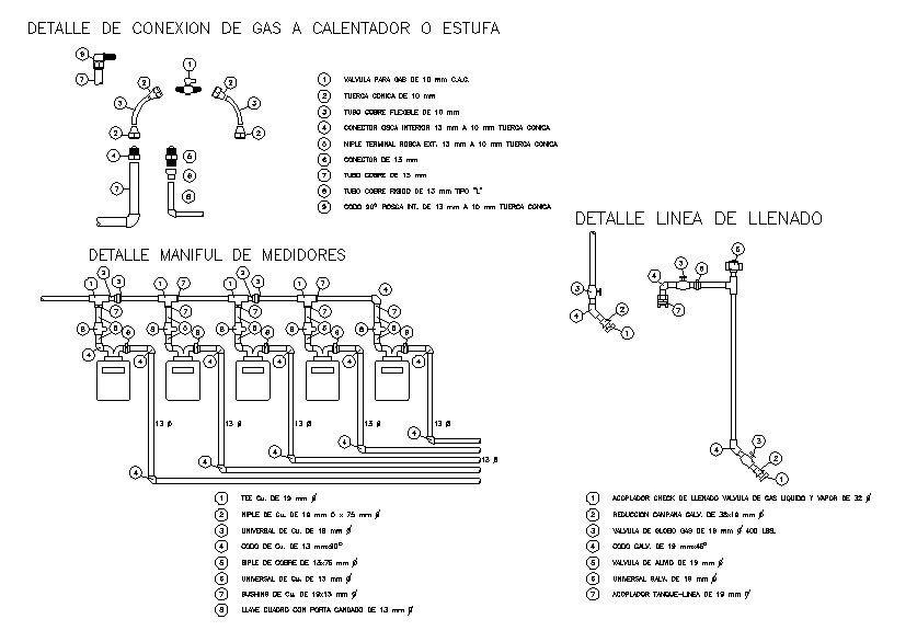
This Piping Detail drawing is provided in AutoCAD DWG format and presents clear technical layouts for gas piping systems used in building services. The drawing includes detailed gas connection layouts to heaters and stoves, showing valves, flexible hoses, connectors, elbows, and threaded joints with precise diameter references. Pipe sizes such as 10 mm and 13 mm are clearly labeled, along with component symbols and connection sequences. The drawing explains correct routing, safety valve placement, and connection methods required for reliable gas distribution within residential or commercial buildings.

Uploaded by:
Jafania Waxy
Tags
Ratings & Reviews
Be the first to share your experience with this product. Your review helps others make better decisions!