Well Construction Detail DWG with Grounding and Measurements
Tags
Ratings & Reviews
Be the first to share your experience with this product. Your review helps others make better decisions!
Description
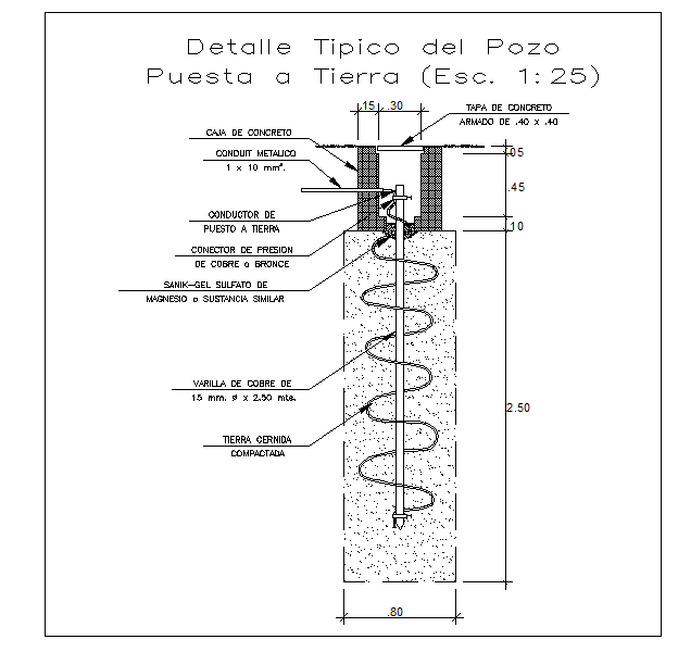
This AutoCAD DWG file provides a complete well detail for water well construction, including grounding installation, concrete casing, and reinforcement specifications. The drawing features precise dimensions for the well depth, width, and placement of copper rods, grounding conductors, and pressure connectors. The file highlights the concrete cover, conduit positioning, and compacted soil base, ensuring structural integrity and electrical safety. All elements are annotated for clarity, providing engineers and architects with a clear step-by-step visual guide for well installation and grounding.
The DWG includes sectional views to show the embedded copper rods, grounding conductors, and the surrounding concrete and soil layers. Every component, including the Sanik-Gel sulfate or similar material, concrete cover, and reinforcement grid, is labeled with exact measurements for accurate implementation. This file is ideal for civil engineers, architects, and construction planners seeking a detailed reference for water well grounding and installation. The layout supports precise scaling, modifications, and integration into larger construction or infrastructure projects.

Uploaded by:
Harriet Burrows
Tags
Ratings & Reviews
Be the first to share your experience with this product. Your review helps others make better decisions!