Sewage Tank Design CAD Drawing with Septic Tank Pipe Details
Ratings & Reviews
Be the first to share your experience with this product. Your review helps others make better decisions!
Description
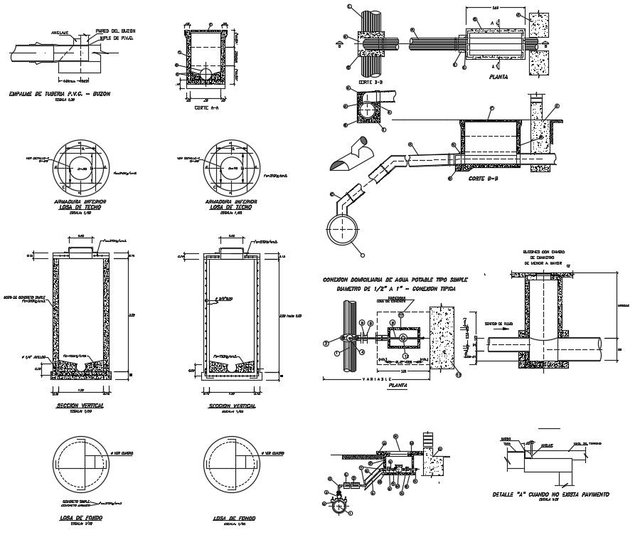
This AutoCAD drawing file provides a detailed sewage tank design CAD drawing showing complete septic tank construction information. The drawing includes plan and sectional views of the sewage tank with clear internal chamber arrangement, inlet and outlet pipe positioning, and ventilation layout. It illustrates concrete wall thickness, base slab depth, partition walls, and manhole cover placement with proper alignment. Sewer pipe blocks are shown with accurate pipe diameters, slope direction, joint connections, and pipe embedment details. The drawing also represents concrete pipe sections, joint sealing methods, and inspection chamber connections required for effective wastewater flow and maintenance.
The sewage tank design CAD drawing is suitable for architects, civil engineers, and builders involved in residential and small commercial sanitation projects. This AutoCAD DWG file supports integration with Revit, 3d Max, and SketchUp for coordination and visualization. With precise measurements for tank length, width, depth, pipe size, and construction levels, the drawing assists in construction documentation, quantity estimation, and on site execution. Accessing this drawing through a Cad bull subscription helps professionals save time and maintain accuracy in sewage system planning and detailing.
File Type:
DWG
File Size:
1.1 MB
Category::
Structure
Sub Category::
Section Plan CAD Blocks & DWG Drawing Models
type:
Gold
Tags
Uploaded by:
Priyanka
Patel
Ratings & Reviews
Be the first to share your experience with this product. Your review helps others make better decisions!