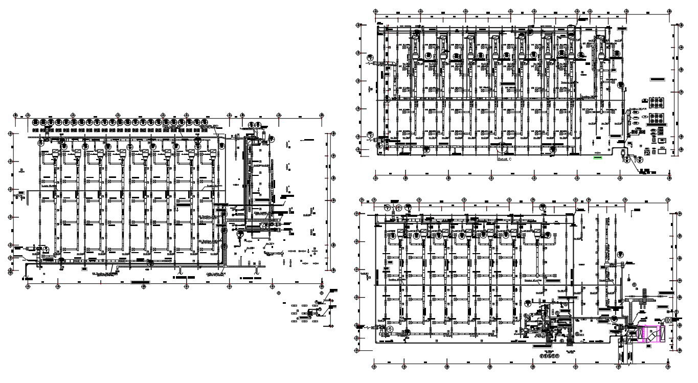
Foundation Layout Plan CAD Drawing With Footing Grid Dimensions
Tags
Ratings & Reviews
Be the first to share your experience with this product. Your review helps others make better decisions!
Description
This foundation layout plan CAD drawing provides a detailed and accurately scaled structural layout prepared for professional construction planning. The drawing includes a clear footing grid arrangement with column positions, center line references, and foundation alignment for load bearing and framed structures. Typical isolated and combined footings are shown with standard footing sizes around 1200 mm by 1200 mm and thickness of approximately 300 mm, ensuring proper load distribution. The layout illustrates column spacing, foundation offsets, and reference dimensions to support precise site execution and structural coordination. Clean drafting and organized annotation make this foundation layout drawing suitable for technical documentation and construction level drawings.
The AutoCAD foundation layout drawing is ideal for civil engineers, architects, and structural designers involved in residential and commercial projects. It allows seamless coordination with column layouts, plinth beams, and superstructure drawings. The drawing focuses strictly on technical foundation details and supports accurate quantity estimation, excavation planning, and reinforcement coordination. With defined dimensions, grid references, and professional drafting standards, this CAD drawing improves workflow efficiency and ensures clarity for foundation planning, approvals, and on site construction execution.
Uploaded by:
helly panchal
Tags
Ratings & Reviews
Be the first to share your experience with this product. Your review helps others make better decisions!