Installation Scheme Detail AutoCAD Drawing with Utility Layout
Tags
Ratings & Reviews
Be the first to share your experience with this product. Your review helps others make better decisions!
Description
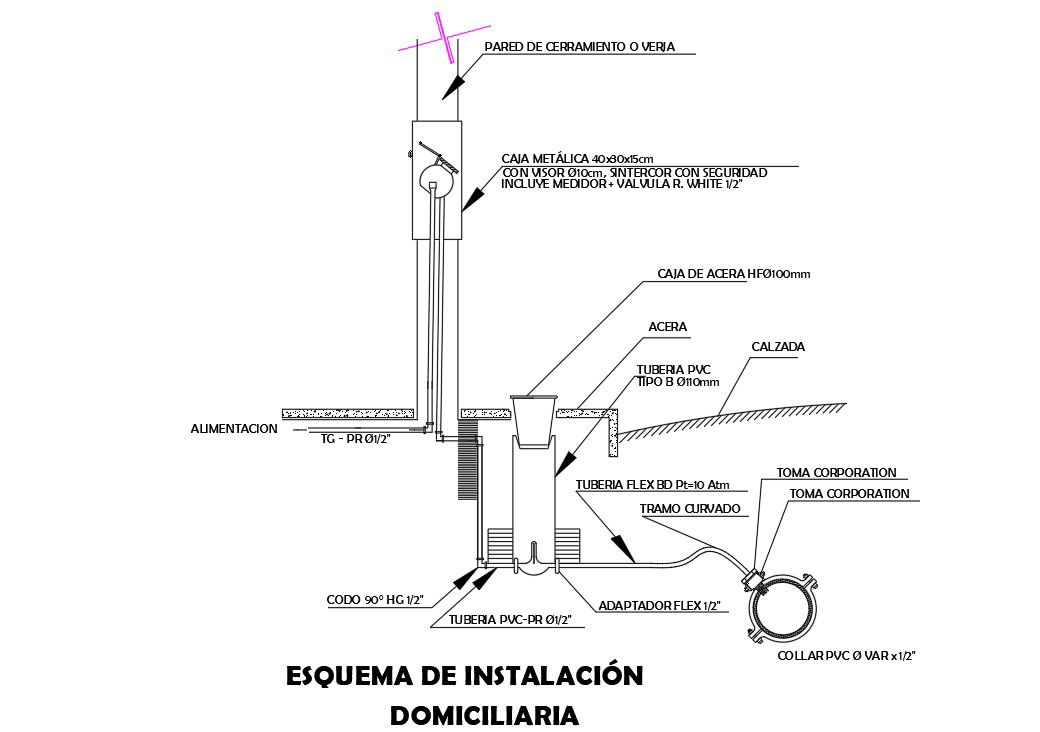
This Installation Scheme Detail DWG drawing provides a complete AutoCAD-based schematic for residential utility installation with clear component layout and fixing details. The drawing illustrates a metal box of size 40x30x15 cm, curb box HF 100 mm, take corporation connection, and routing through the siding wall or fence. Pipe alignment, vertical and horizontal transitions, and connection points are clearly defined to ensure accurate installation and coordination with site conditions. Dimensions for box placement, pipe diameter, elbow positioning, and ground level references are shown to support proper execution during construction and service connections.
The Installation Scheme Detail DWG File also includes section views and annotated details explaining PVC pipe routing, flexible pipe connections, adapters, collars, and fixing methods. Exterior and interior junctions are clearly marked to help civil engineers, builders, and utility planners understand installation flow and material coordination. The drawing follows standard AutoCAD layering, consistent scale, and clear annotations for easy editing and reuse. This installation scheme drawing is ideal for professionals who require reliable utility installation details with accurate measurements, component specifications, and construction-ready documentation for residential and boundary wall service layouts.
Uploaded by:
Priyanka Patel
Tags
Ratings & Reviews
Be the first to share your experience with this product. Your review helps others make better decisions!