Gas Meter Detail Drawing with Concrete Base Floor Level Design
Tags
Ratings & Reviews
Be the first to share your experience with this product. Your review helps others make better decisions!
Description
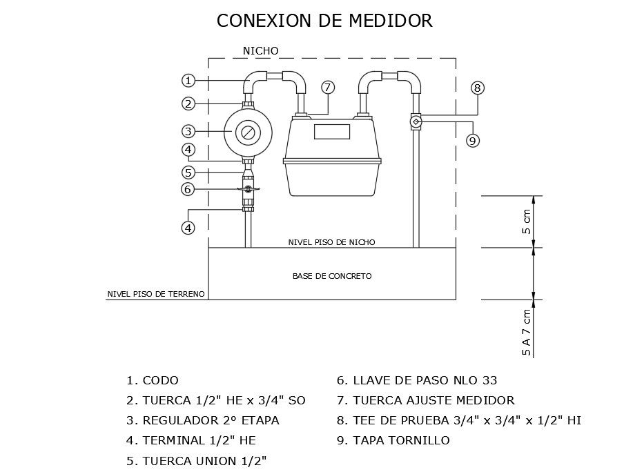
This Gas Meter Detail AutoCAD drawing provides a clear, well-defined layout of a gas meter connection installed in a niche area. The drawing illustrates the gas meter positioned over a concrete base with clear indications of the ground floor level and niche floor level. Vertical measurements of 5 cm and 5-7 cm are shown to define the installation height accuracy. The drawing includes all essential gas connection components such as elbow joints, 1/2 inch and 3/4 inch nuts, terminal fittings, union nuts, and a second-stage gas regulator. A step valve NLO 33 and meter adjustment nut are also clearly labeled to ensure safe and controlled gas flow.
The detailed schematic further shows the test tee connection sized 3/4 inch by 3/4 inch by 1/2 inch, along with a cover screw for secure closure. Pipe routing inside the niche is clearly represented for practical site execution and coordination with architectural or service layouts. This AutoCAD DWG file is suitable for architects, civil engineers, interior designers, and builders working on residential or commercial gas service installations. Available through cadbull.com subscription, this gas meter detail drawing supports accurate drafting, utility coordination, and standardized gas meter installation documentation.
Uploaded by:
Priyanka Patel
Tags
Ratings & Reviews
Be the first to share your experience with this product. Your review helps others make better decisions!