Steel Joint Wall Detail Drawing with Reinforced Concrete Beam
Tags
Ratings & Reviews
Be the first to share your experience with this product. Your review helps others make better decisions!
Description
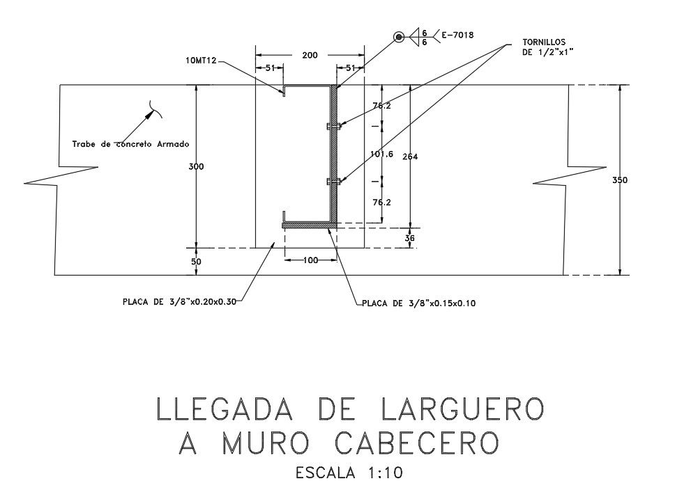
This Steel Joint Wall AutoCAD drawing illustrates a precise structural connection detail between a steel member and a reinforced concrete wall. The drawing shows the arrival of a steel beam at the head wall with a clear section view at scale 1:10. Detailed dimensions indicate a wall height of 350 mm and a concrete beam depth of 300 mm with a base offset of 50 mm. The steel profile connection is fixed using 1/2 inch by 1 inch bolts, with exact vertical spacing values of 76.2 mm, 101.6 mm, and an overall fixing height of 264 mm. Plate sizes are clearly specified, including a 3/8 inch thick plate measuring 0.20 x 0.30 m and an additional 3/8 inch plate of 0.15 x 0.10 m for load transfer.
The drawing also highlights reinforcement notation, steel embedment depth of 100 mm, and a horizontal spacing of 200 mm between fixing points. Fastening tolerances of 5 mm are marked for accurate site alignment. This AutoCAD DWG file is useful for architects, civil engineers, and structural designers working on steel-to-concrete joint detailing. Available through cadbull.com subscription, this steel joint wall drawing supports professional CAD documentation, structural coordination, and reliable execution of reinforced concrete and steel connection details.
Uploaded by:
Priyanka Patel
Tags
Ratings & Reviews
Be the first to share your experience with this product. Your review helps others make better decisions!