Drainage System Plan DWG File with Pipe Layout and Section Details
Tags
Ratings & Reviews
Be the first to share your experience with this product. Your review helps others make better decisions!
Description
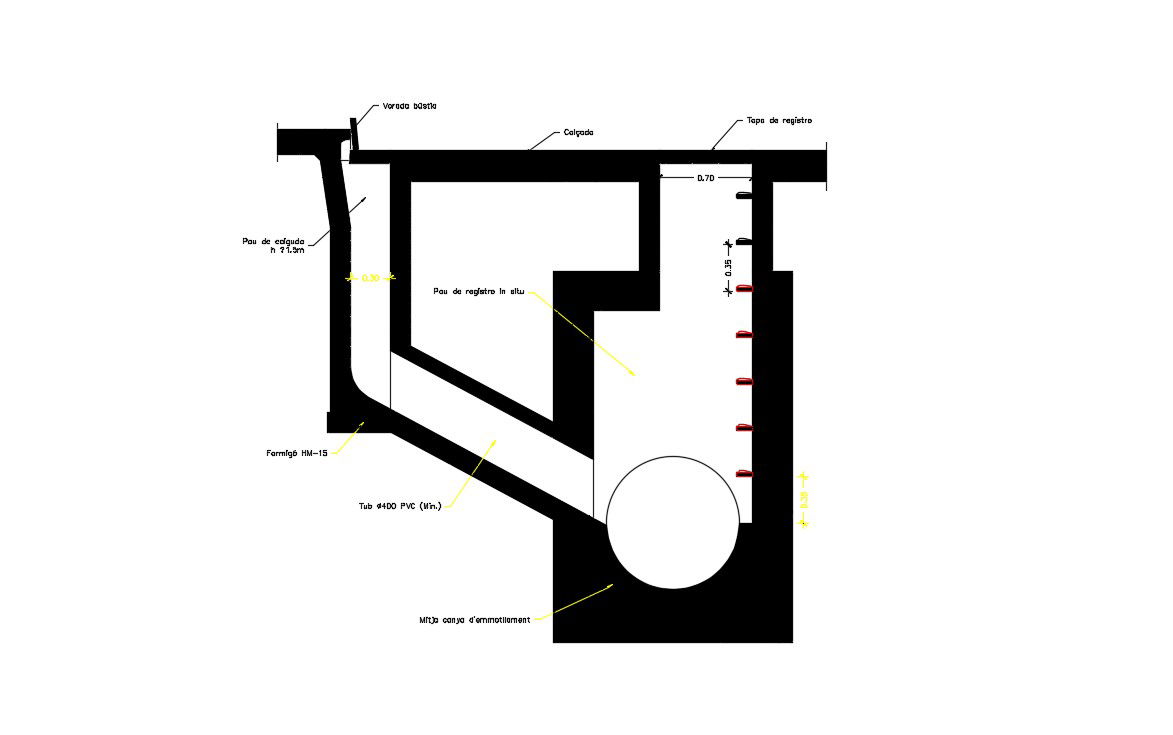
This drainage system plan DWG file provides a complete AutoCAD drawing of underground and surface drainage networks for residential, commercial, and infrastructure projects. The file includes detailed pipe layouts, inlet and outlet connections, half-round molding, curb mailbox alignment, register cap details, and slope markings for proper water flow. Longitudinal and cross-sectional views are provided with accurate measurements to support efficient drainage planning. The drawing also shows PVC pipe routing, inspection chamber placement, and structural support details for long-term durability.
The drainage system design is suitable for architects, civil engineers, builders, and infrastructure planners who require precise CAD documentation. It includes installation references, depth indicators, material specifications, and maintenance access points. The AutoCAD file can be easily edited and integrated with 3D Max, Revit, and SketchUp for visualization and coordination. This DWG file helps improve construction accuracy, minimize waterlogging risks, and optimize stormwater management in building and site development projects.
Uploaded by:
Priyanka Patel
Tags
Ratings & Reviews
Be the first to share your experience with this product. Your review helps others make better decisions!