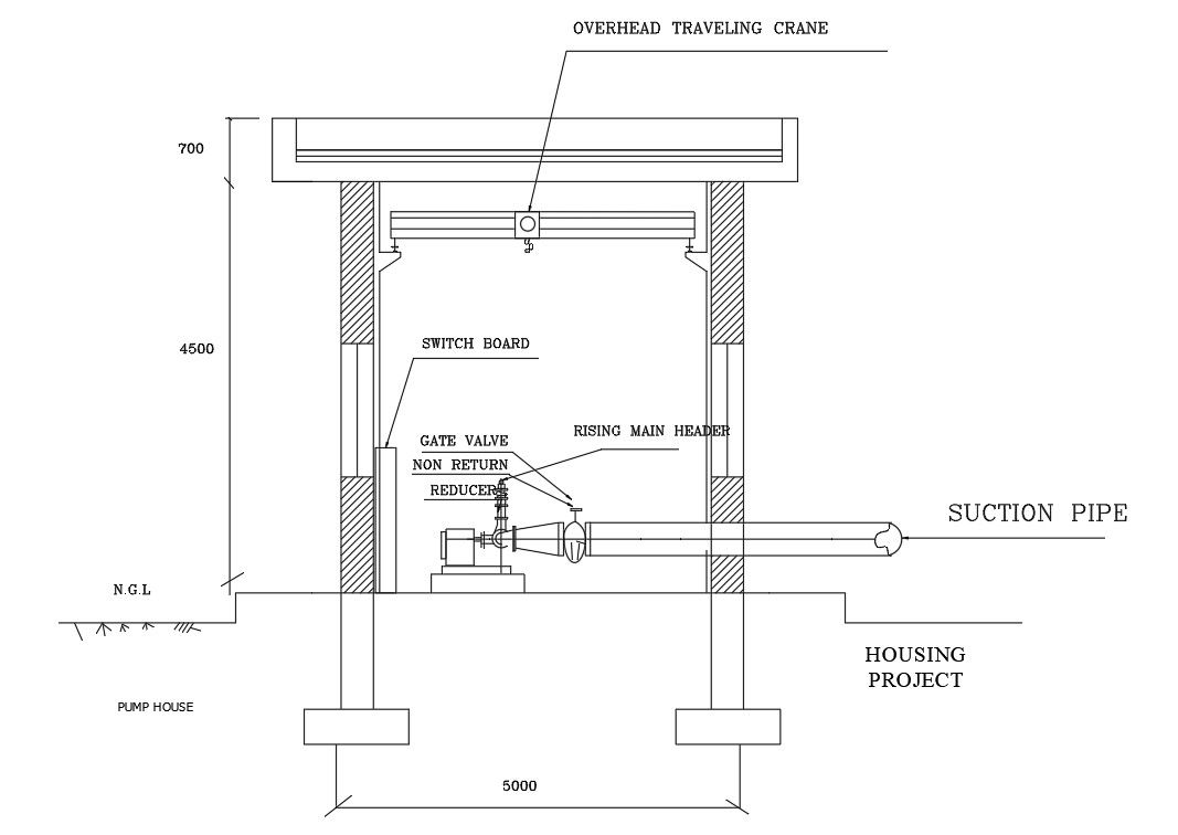
Pump House Layout Drawing with Suction Pipe and Header Details
Tags
Ratings & Reviews
Be the first to share your experience with this product. Your review helps others make better decisions!
Description
This pump house layout drawing presents a complete mechanical and structural arrangement with clearly defined components, including switchboard, suction pipe, rising main header, reducer, non-return valve, and gate valve system. The section drawing shows a pump installation height of approximately 4500 mm from natural ground level, ensuring proper clearance for maintenance and operation. The overall structure width is around 5000 mm, providing adequate working space for equipment handling and inspection. Overhead traveling crane positioning is included for lifting and servicing heavy pump units. Foundation depth, column alignment, and equipment base levels are accurately detailed. All dimensions and component placements are drafted in AutoCAD format for professional use and precise execution.

Uploaded by:
helly panchal
Tags
Ratings & Reviews
Be the first to share your experience with this product. Your review helps others make better decisions!