Pumping Station Layout with Penstock and Surge Shaft AutoCAD Drawing
Tags
Ratings & Reviews
Be the first to share your experience with this product. Your review helps others make better decisions!
Description
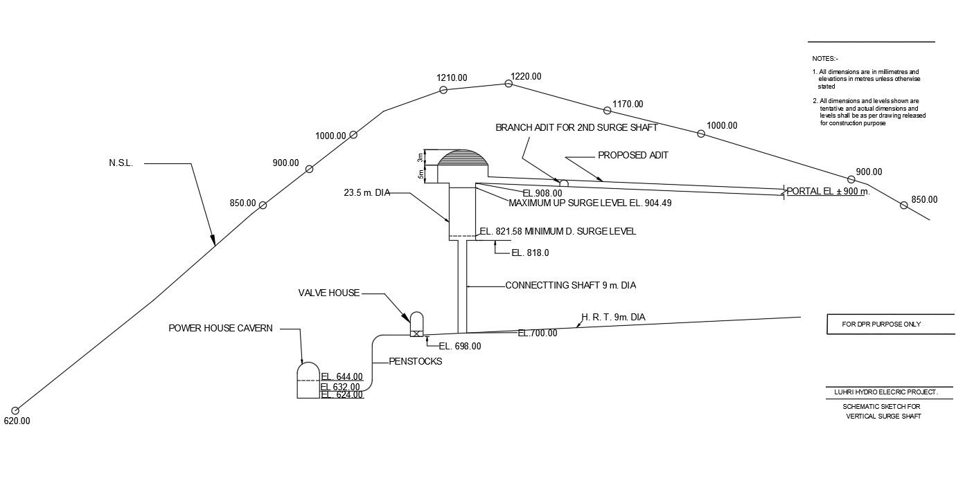
This pumping station layout with penstock and surge shaft AutoCAD drawing provides complete technical documentation for hydroelectric and water management infrastructure projects. The drawing includes power house cavern location, vertical surge shaft details, connecting shaft layout, penstock alignment, valve house positioning, and portal entry levels. It clearly represents elevation levels, shaft diameters, tunnel gradients, and structural transitions between underground and surface components. All drawings are prepared with accurate measurements, scale references, and engineering annotations to support construction planning, hydraulic analysis, and project approvals. This AutoCAD-DWG file is suitable for pumping stations and hydropower facilities.

Uploaded by:
helly panchal
Tags
Ratings & Reviews
Be the first to share your experience with this product. Your review helps others make better decisions!