Electrical Substation Layout with Transformer and Circuit Details
Tags
Ratings & Reviews
Be the first to share your experience with this product. Your review helps others make better decisions!
Description
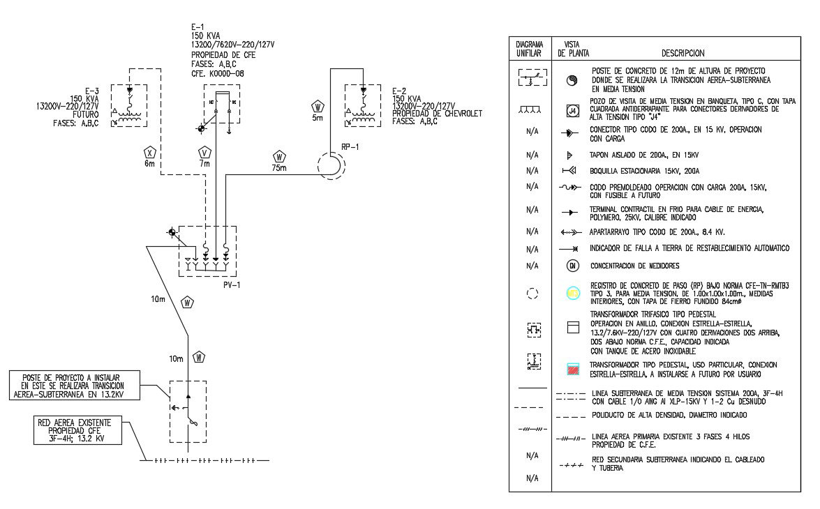
This AutoCAD drawing provides a complete electrical substation layout, detailing transformers, circuit breakers, underground and overhead lines, and all connection points. The schematic illustrates the flow of electricity from generation through transmission to distribution, with precise measurements and a clear representation of high voltage components, medium voltage systems, and protective devices. Architects, civil engineers, interior designers, and builders can use this DWG file for planning substation installations, designing layouts, and coordinating construction projects efficiently. The diagram includes pedestal transformers, star-delta connections, fuse placements, and detailed annotations for each electrical component. Substation wiring paths, protective relays, and measurement points are all labeled for clarity, ensuring accurate implementation and safety compliance. This file supports AutoCAD, 3ds Max, Revit, and SketchUp workflows, providing professionals with comprehensive electrical data to enhance project accuracy and reduce errors during construction. The detailed substation layout is essential for both educational purposes and practical applications in industrial and commercial projects, making it a valuable resource for electrical system planning and design.
Uploaded by:
Priyanka Patel
Tags
Ratings & Reviews
Be the first to share your experience with this product. Your review helps others make better decisions!