Industrial Exhaust Fan System Cad Drawing with Valve Filter Plan
Tags
Ratings & Reviews
Be the first to share your experience with this product. Your review helps others make better decisions!
Description
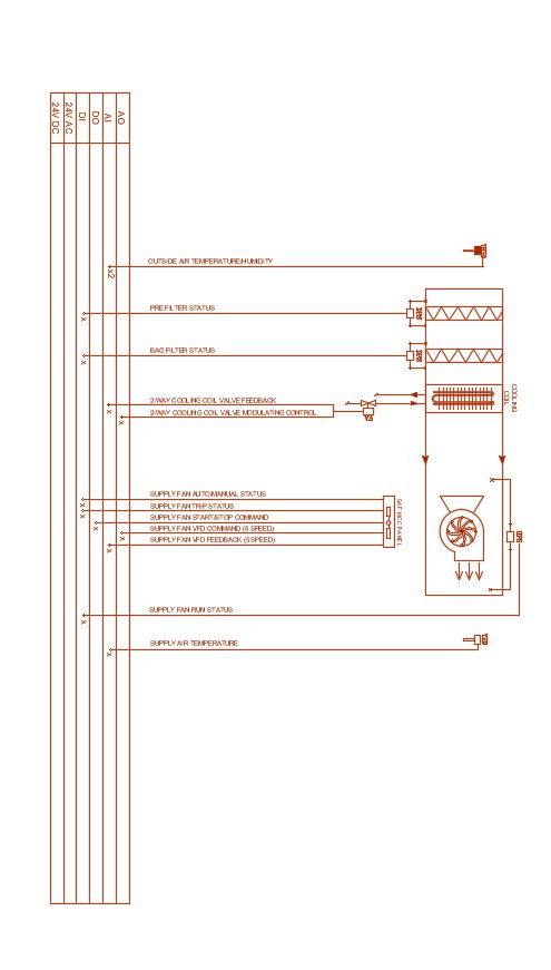
Industrial exhaust fan system cad drawing includes complete layout details of valve blocks, filter pipe, meter gauge, pressure meter, control panel lines, fan motor unit, air flow direction, and connected service components. The drawing shows equipment linking paths, monitoring points, and system control connections for mechanical ventilation planning. Useful for architects, civil engineers, builders, HVAC planners, and drafting professionals needing clear exhaust fan system references. This file supports accurate coordination, equipment placement, and industrial air movement design for factory, plant, and commercial service projects with technical CAD details.

Uploaded by:
akansha ghatge
Tags
Ratings & Reviews
Be the first to share your experience with this product. Your review helps others make better decisions!