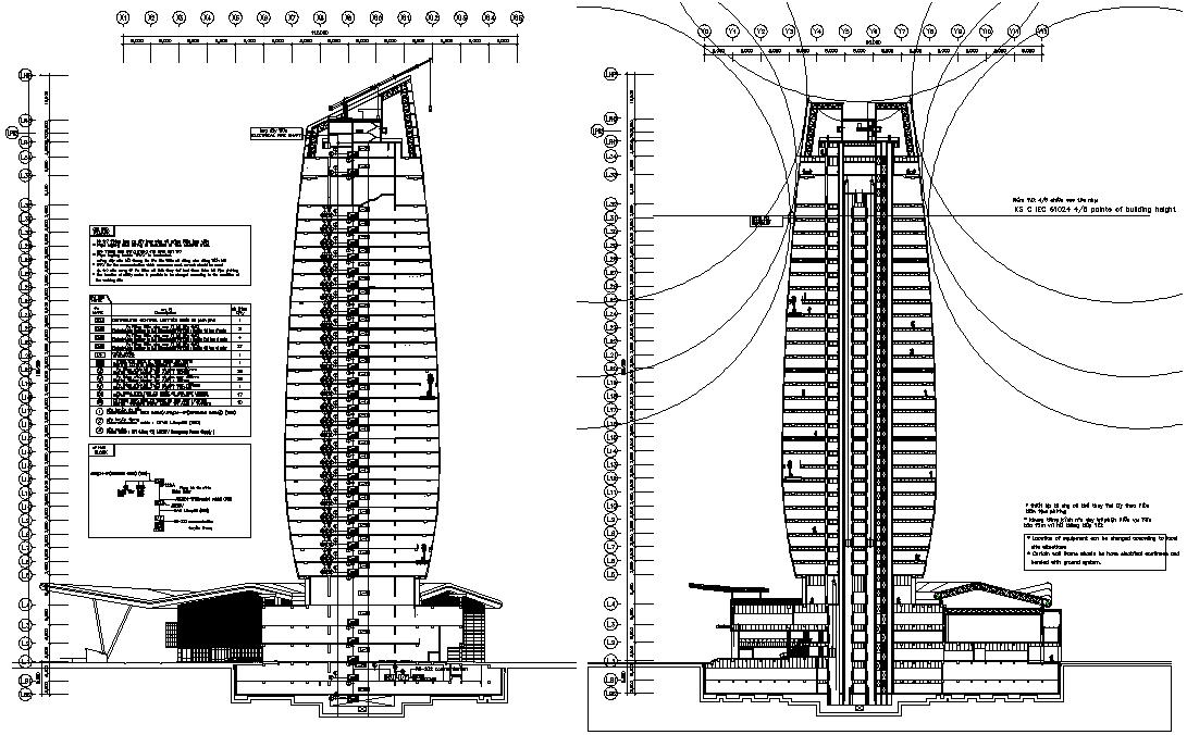
High Rise Building Section and Elevation Layout with Telemetering
Tags
Ratings & Reviews
Be the first to share your experience with this product. Your review helps others make better decisions!
Description
This high rise building section and elevation layout is a detailed 2D AutoCAD drawing prepared for architectural and building services coordination. The drawing presents sectional and elevation views with clearly marked telemetering equipment positions integrated within the building structure. Vertical sections illustrate floor levels height relationships and equipment placement accuracy to support system planning. Elevation views define external proportions and alignment of telemetering components with structural elements. Dimension annotations are provided to explain level heights spacing and equipment locations ensuring clarity for architects and civil engineers during planning and coordination.
The sectional layout further explains internal building organization with telemetering components shown in relation to floors walls and service zones. Equipment symbols and labels are arranged clearly to improve readability and interpretation. Measurements support accurate positioning and installation planning within a high rise context. The drawing helps builders and designers understand how telemetering systems integrate with the building section and elevation. This CAD drawing is suitable for AutoCAD based workflows and can be referenced in Rivet 3D Max and Google SketchUp projects for high rise building documentation section elevation coordination and telemetering layout planning.

Uploaded by:
AS SETHUPATHI
Tags
Ratings & Reviews
Be the first to share your experience with this product. Your review helps others make better decisions!