Butt Weld Isometric Piping Section AutoCAD Drawing Details Layout
Ratings & Reviews
Be the first to share your experience with this product. Your review helps others make better decisions!
Description
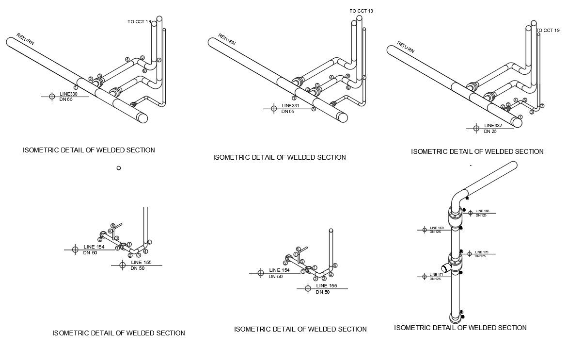
This AutoCAD 2D DWG drawing file presents detailed butt weld isometric section drawings used in piping and mechanical layout projects. The drawing includes six different butt-welded connection configurations, clearly illustrated in an isometric view for accurate understanding of pipe routing and joint execution. Each welded section shows pipe direction, return lines, equipment connections, and line references with DN sizes such as DN 25, DN 50, DN 65, DN 85, and DN 125. Welding locations, joint numbering, and component alignment are clearly marked, making the drawing suitable for fabrication, installation, and site coordination purposes.
The DWG file is ideal for use in industrial piping layouts, mechanical services drawings, and plant engineering documentation. It supports architects, civil engineers, mechanical engineers, and fabrication professionals who require precise welded joint representation. The drawing helps ensure correct welding sequence, pipe material coordination, and installation clarity during execution. This AutoCAD file can be directly integrated into construction drawings, shop drawings, and fabrication plans. Access to this professional CAD resource is available through a Cadbull subscription, offering reliable and industry-ready AutoCAD drawing content.
File Type:
DWG
File Size:
134 KB
Category::
Structure
Sub Category::
Section Plan CAD Blocks & DWG Drawing Models
type:
Gold
Tags
Uploaded by:
Justine
Ratings & Reviews
Be the first to share your experience with this product. Your review helps others make better decisions!