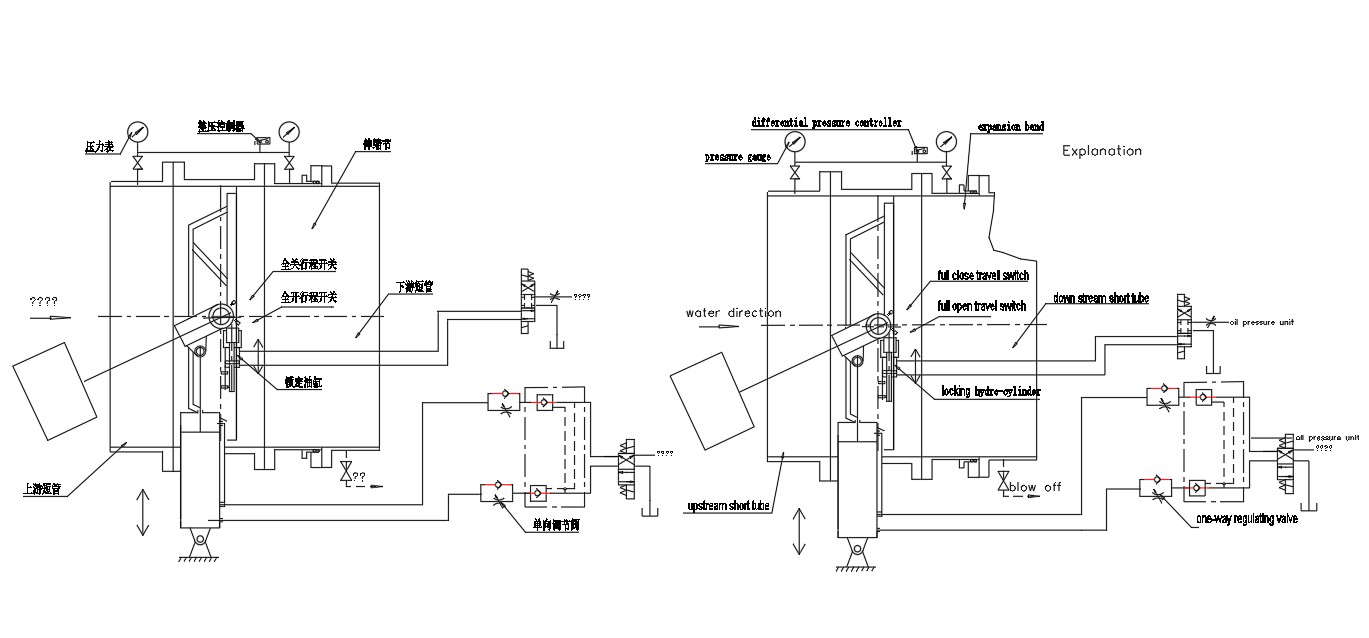
AutocadD DWG drawing Details of hydraulic control system.The parts of Hydraulic control system are clearly explained in this Drawing.The valve and the automated parts are all in the off-position in this drawing.When open valve,solenoid directional valve 4DT get electricity, the electrical motor starts,the pressure oil in oil pump enters the servomotor down cavity, push the piston rod to overhang, at the same time hold the heavy bob,the solenoid direction valve 6DT get electricitythen the change pressure oil enters the locking oil tank down cavity push piston rod to overhang then to lock. When close valve the solenoid directional valve 5DT get electricity,pressure oil in power accumulator enters the locking oil tank up cavityremove lockin,the solenoid directional valve 3DT get electricity,pressure oil in power accumulator enters the locking oil tank up cavity When close valve the solenoid directional valve 3DT get electricity,pressure oil in power accumulator enters servomotor up cavity. Push the piston rod indentation,closes the valve under servomotor and the heavy bob function.Download the DWG AutoCAD file.Thanks for Downloading AutoCAD DWG and other CAD program files from our website.


