Continuous Beam Reinforcement CAD Drawing with Typical Section Details
Tags
Ratings & Reviews
Be the first to share your experience with this product. Your review helps others make better decisions!
Description
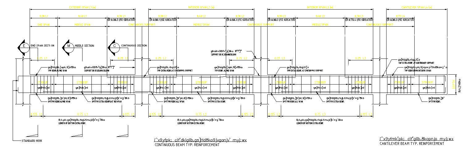
This continuous beam reinforcement AutoCAD drawing provides a comprehensive 2D representation of typical reinforcement detailing used in RCC beam design. The CAD file clearly illustrates end span sections, middle span sections, continuous sections, and cantilever beam reinforcement arrangements. Reinforcement placement for top bars, bottom bars, extra reinforcement, and stirrups is accurately shown with clear notation. Span lengths, reinforcement cut-off points, hook details, and anchorage lengths are marked to support structural clarity and execution accuracy. The drawing also explains reinforcement behavior at supports and beam-column junctions for proper load transfer.
The drawing further includes typical reinforcement layouts for continuous beams with multiple spans, showing interior span detailing and cantilever support conditions. Dimension references, section symbols, and labeling make this drawing suitable for structural working drawings and site execution. This AutoCAD DWG file is useful for civil engineers, structural engineers, architects, and builders involved in RCC structure detailing. The drawing supports reinforcement planning, quantity estimation, and construction documentation. Access through a Cadbull subscription allows professionals to edit and reuse this CAD block in AutoCAD, Revit, 3D Max, and Google SketchUp workflows.

Uploaded by:
AS SETHUPATHI
Tags
Ratings & Reviews
Be the first to share your experience with this product. Your review helps others make better decisions!