Shell Splice Detail DWG With 5m Diameter Shell And 6mm Plate Thickness
Ratings & Reviews
Be the first to share your experience with this product. Your review helps others make better decisions!
Description
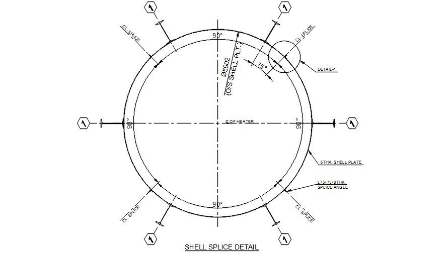
The shell splice detail DWG drawing provides a detailed AutoCAD 2D technical representation of a circular shell structure used in industrial tanks, pressure vessels, and cylindrical structural systems. This drawing illustrates the splice connection arrangement for a shell with a diameter of 5 meters. The shell plate thickness is specified as 6 mm, which forms the outer cylindrical surface of the structure. The drawing also includes splice angle components sized L75 x 75 x 6 mm that are used to connect the shell plate segments securely. The circular shell layout is shown with multiple splice connection points distributed evenly around the circumference, ensuring structural stability and proper load transfer between shell sections. The drawing also indicates centerline splice references and angular spacing measurements, such as 90-degree and 15-degree angles to define the exact splice positioning.
Tags
Uploaded by:
Guptil
Ratings & Reviews
Be the first to share your experience with this product. Your review helps others make better decisions!