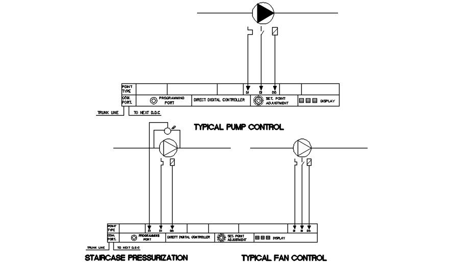
Typical Pump Control System DWG With Fan And Staircase Pressurization
Ratings & Reviews
Be the first to share your experience with this product. Your review helps others make better decisions!
Description
The typical pump control system DWG drawing provides a detailed AutoCAD 2D schematic illustrating the control arrangement used for pumps, fans, and staircase pressurization systems in building mechanical services. This drawing clearly shows the layout of the pump control system connected with a direct digital controller that manages operational signals and system monitoring. Key control components such as programming port, display interface, trunk communication line, and set point adjustment controls are illustrated to demonstrate how system parameters are configured and monitored. The diagram also indicates digital input and output connections used for transmitting operational signals between the pump equipment and the building automation control panel.
Tags
Uploaded by:
Guptil
Ratings & Reviews
Be the first to share your experience with this product. Your review helps others make better decisions!