Valve Vent Detail AutoCAD Drawing with Dimensions and Pipe Reduction
Tags
Ratings & Reviews
Be the first to share your experience with this product. Your review helps others make better decisions!
Description
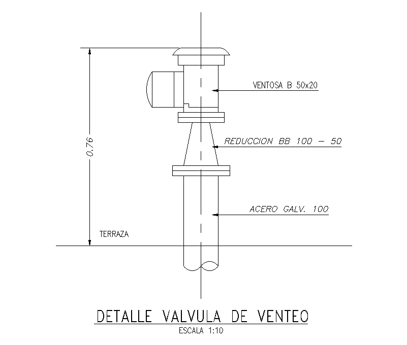
This AutoCAD drawing presents a detailed valve vent assembly used in plumbing and mechanical service installations. The drawing clearly illustrates the valve vent detail with vertical pipe alignment, showing a vent valve of size 50x20 connected through a BB reduction from 100 to 50. A galvanized steel pipe of 100 mm diameter is indicated, extending vertically from the terrace level with an overall visible height of approximately 0.76 m. All main components are labeled with technical naming, making the drawing suitable for a precise understanding of valve positioning and pipe transitions. The layout is clean and focuses entirely on the valve configuration without unnecessary elements.
The drawing is prepared in a 2D AutoCAD format and follows a scale of 1:10, ensuring accurate interpretation of proportions and connections. Dimension lines, centerlines, and component annotations help architects, civil engineers, and mechanical planners understand installation intent and coordination requirements. This valve vent detail drawing is useful for plumbing layouts, terrace service planning, and mechanical detailing in residential and commercial projects. The DWG file supports integration into AutoCAD, Revit, and other CAD-based workflows, making it a reliable reference for construction documentation and technical coordination.
Uploaded by:
Rachna Jilka
Tags
Ratings & Reviews
Be the first to share your experience with this product. Your review helps others make better decisions!