Sewer Camera CAD Drawing for Drainage Inspection Layout Plan
Tags
Ratings & Reviews
Be the first to share your experience with this product. Your review helps others make better decisions!
Description
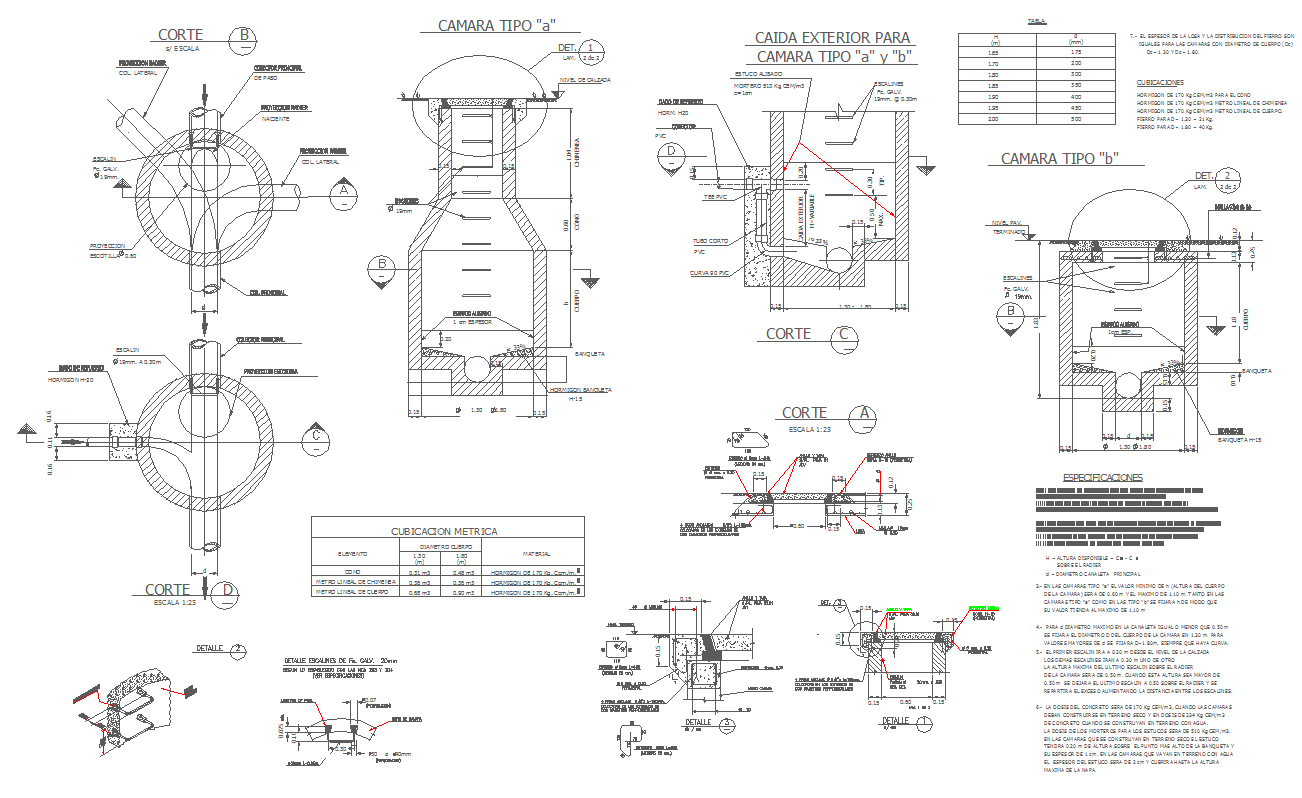
The sewer camera CAD drawing provides a clear technical layout used for drainage inspection and underground pipeline monitoring. This sewer camera CAD drawing is prepared for civil engineering professionals who require precise drafting references for inspection systems used in sewer and drainage networks. The drawing illustrates the sewer inspection camera layout, including camera placement concept, inspection direction, and connection with sewer pipelines for effective underground assessment. It helps architects, civil engineers, builders, and infrastructure planners visualize how inspection cameras are integrated into drainage systems for maintenance and monitoring. The AutoCAD drawing supports professional CAD workflows and can be easily modified for project planning, construction documentation, or technical presentations. Dimensions are not specified in the drawing, but the structural layout clearly represents the inspection arrangement.

Uploaded by:
K.H.J Jani
Tags
Ratings & Reviews
Be the first to share your experience with this product. Your review helps others make better decisions!