Centrifuges Pump DWG File with Copper Connectors and Check Valve
Tags
Ratings & Reviews
Be the first to share your experience with this product. Your review helps others make better decisions!
Description
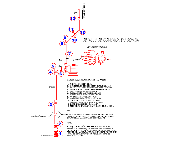
This centrifuge's pump DWG file provides detailed AutoCAD drawings, including an external rope copper connector 38mm, a reduction copper hood 38mm x 25mm, and all threaded nipples galvanized from 10cm long, except for the one connecting to the check valve. The file includes precise measurements of pump dimensions, valve placement, connector alignment, and piping layout, making it ideal for architects, civil engineers, mechanical designers, and builders. Each section displays check valve columns, pipe intersections, and assembly details to ensure accurate installation in industrial and commercial hydraulic systems. Compatible with AutoCAD, 3d Max, Revit, and Google SketchUp, this CAD drawing offers comprehensive guidance for pump integration, plumbing coordination, and technical reference. Detailed sectional views and annotations allow professionals to streamline planning, installation, and maintenance workflows. This DWG file is a valuable resource for precise centrifuge pump layout, connector placement, and hydraulic system design, supporting efficient project execution and accurate engineering standards.
Uploaded by:
Priyanka Patel
Tags
Ratings & Reviews
Be the first to share your experience with this product. Your review helps others make better decisions!