Footing CAD Drawing with Structural Layout and Reinforcement Detail
Tags
Ratings & Reviews
Be the first to share your experience with this product. Your review helps others make better decisions!
Description
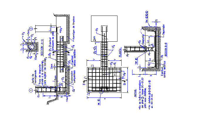
The Footing CAD Drawing with Structural Layout and Reinforcement Detail provides a detailed representation of foundation footings used in building construction. This CAD drawing illustrates isolated and combined footing layouts, showing the positioning of columns, slab thickness, and reinforcement details, including rebar sizes, spacing, and stirrup placement. The plan and sectional views highlight the foundation dimensions, concrete cover, and structural alignment to ensure stability and proper load distribution. Footing design is critical for transferring structural loads safely to the ground while maintaining compliance with civil engineering standards and construction codes. Standard footing dimensions vary depending on soil conditions, building loads, and column sizes, ensuring safety and durability for residential, commercial, and industrial structures.

Uploaded by:
Eiz Luna
Tags
Ratings & Reviews
Be the first to share your experience with this product. Your review helps others make better decisions!