Sewer Inlet Drainage CAD Layout with Plan and Elevation Measurements
Tags
Ratings & Reviews
Be the first to share your experience with this product. Your review helps others make better decisions!
Description
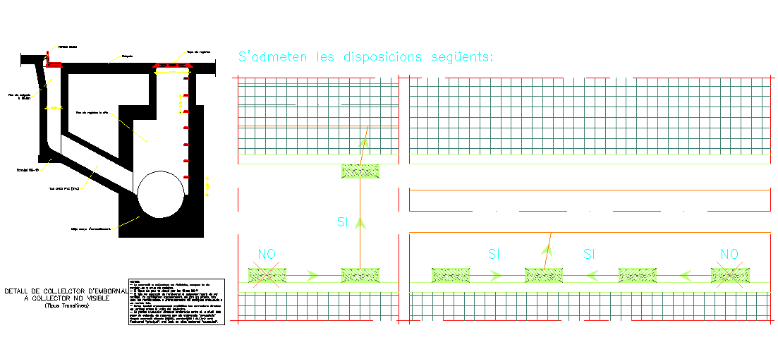
This AutoCAD drawing presents a detailed sewer inlet drainage layout showing the structure used to collect surface water and direct it into underground drainage pipelines. The drawing includes a clear plan view and elevation view illustrating the arrangement of the sewer inlet chamber, pipe connection alignment, and dimensional measurements required for installation. Architects, civil engineers, and infrastructure designers can use this drawing to understand how the inlet structure integrates with drainage systems for effective water flow management. Clear annotations explain inlet positioning, structural alignment, and pipe entry arrangement required for efficient drainage operation.
Uploaded by:
apurva munet
Tags
Ratings & Reviews
Be the first to share your experience with this product. Your review helps others make better decisions!