Lift Section Drawing Design in DWG File for Structural Planning
Description
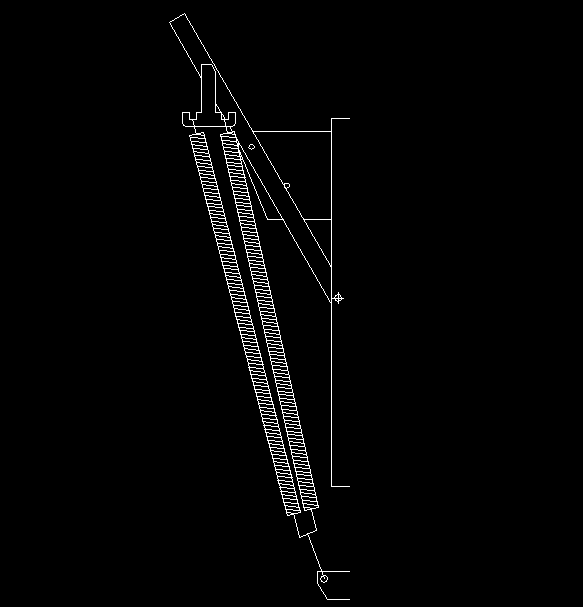
This Lift Section CAD Drawing in DWG format presents a detailed sectional view of a lift mechanism, ideal for architectural and structural planning. The drawing includes vertical alignment details, shaft arrangement, guide rail positions, spring systems, and lift cabin alignment, providing engineers and architects with precise technical references. Each component is represented with clean linework, offering clarity for construction and mechanical installation documentation.
The section drawing measures approximately 3.2 meters in height, maintaining accuracy for standard residential or mid-rise building lifts. It clearly defines key lift components, making it useful for design verification, MEP coordination, and architectural detailing. This DWG file is suitable for architects, civil engineers, and building contractors working on vertical circulation systems. The lift section layout is also compatible with software like Revit, SketchUp, and 3ds Max, allowing for 3D visualization and further modeling development. Perfect for design professionals seeking high-quality lift section references, this CAD drawing ensures precision, consistency, and practical application in real-world building projects.
File Type:
DWG
File Size:
10 KB
Category::
Mechanical and Machinery
Sub Category::
Elevator Details
type:
Gold

Uploaded by:
john
kelly
