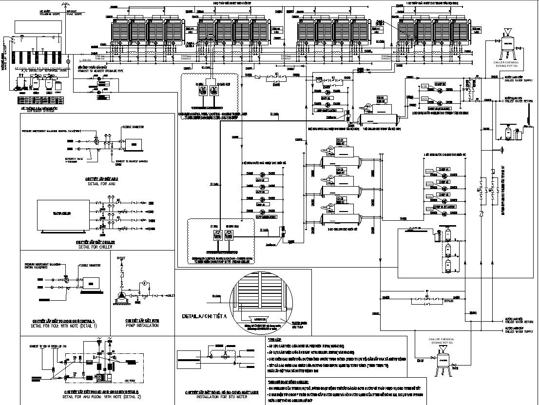
SCHEMATIC DIAGRAM FOR CHILLER SYSTEM
Tags
Ratings & Reviews
Be the first to share your experience with this product. Your review helps others make better decisions!
Description
This Architectural Drawing is of SCHEMATIC DIAGRAM FOR CHILLER SYSTEM. A chiller is a machine that removes heat from a liquid coolant via a vapor-compression, adsorption refrigeration, or absorption refrigeration cycles. This liquid can then be circulated through a heat exchanger to cool equipment, or another process stream (such as air or process water). A chiller works on the principle of vapor compression or vapor absorption. Chillers provide a continuous flow of coolant to the cold side of a process water system at a desired temperature of about 50°F (10°C). The purpose of chillers, whether they're industrial or HVAC, is to move heat from one location and transport it to another place to chill. Chillers tend to use either water or another type of liquid to process it through the piece of equipment they're trying to chill. For more details and information download the drawing file.

Uploaded by:
Eiz Luna
Tags
Ratings & Reviews
Be the first to share your experience with this product. Your review helps others make better decisions!