Typical Sump Plan Layout with Dimensions AutoCAD 2D DWG Drawing
Tags
Ratings & Reviews
Be the first to share your experience with this product. Your review helps others make better decisions!
Description
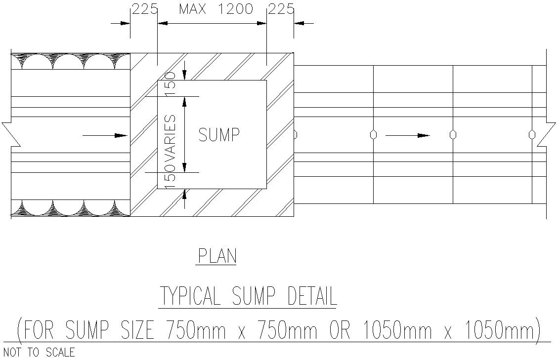
This AutoCAD 2D drawing shows a typical sump plan layout prepared for plumbing and drainage design coordination. The plan illustrates the top view of a sump chamber with clear internal and external dimensions. The drawing includes standard sump sizes of approximately 750 mm × 750 mm and 1050 mm × 1050 mm, along with reinforcement thickness of 225 mm around the sump walls. The maximum overall sump size is indicated up to 1500 mm, helping designers understand spatial requirements and construction limits. Flow direction arrows and surrounding structural context are also shown to support accurate placement within site or building layouts.
The DWG file is suitable for architects, civil engineers, plumbing engineers, builders, and CAD professionals involved in water management and drainage system planning. This typical sump plan CAD drawing helps visualize chamber sizing, reinforcement layout, and integration with pipelines or drainage channels. The clean 2D linework allows easy scaling, editing, and use within larger architectural, plumbing, or infrastructure drawings using AutoCAD, 3D Max, Revit, and Google SketchUp. Access through a cadbull.com subscription enables professionals to use reliable sump plan details for design reference, coordination, and construction documentation.

Uploaded by:
Eiz Luna
Tags
Ratings & Reviews
Be the first to share your experience with this product. Your review helps others make better decisions!