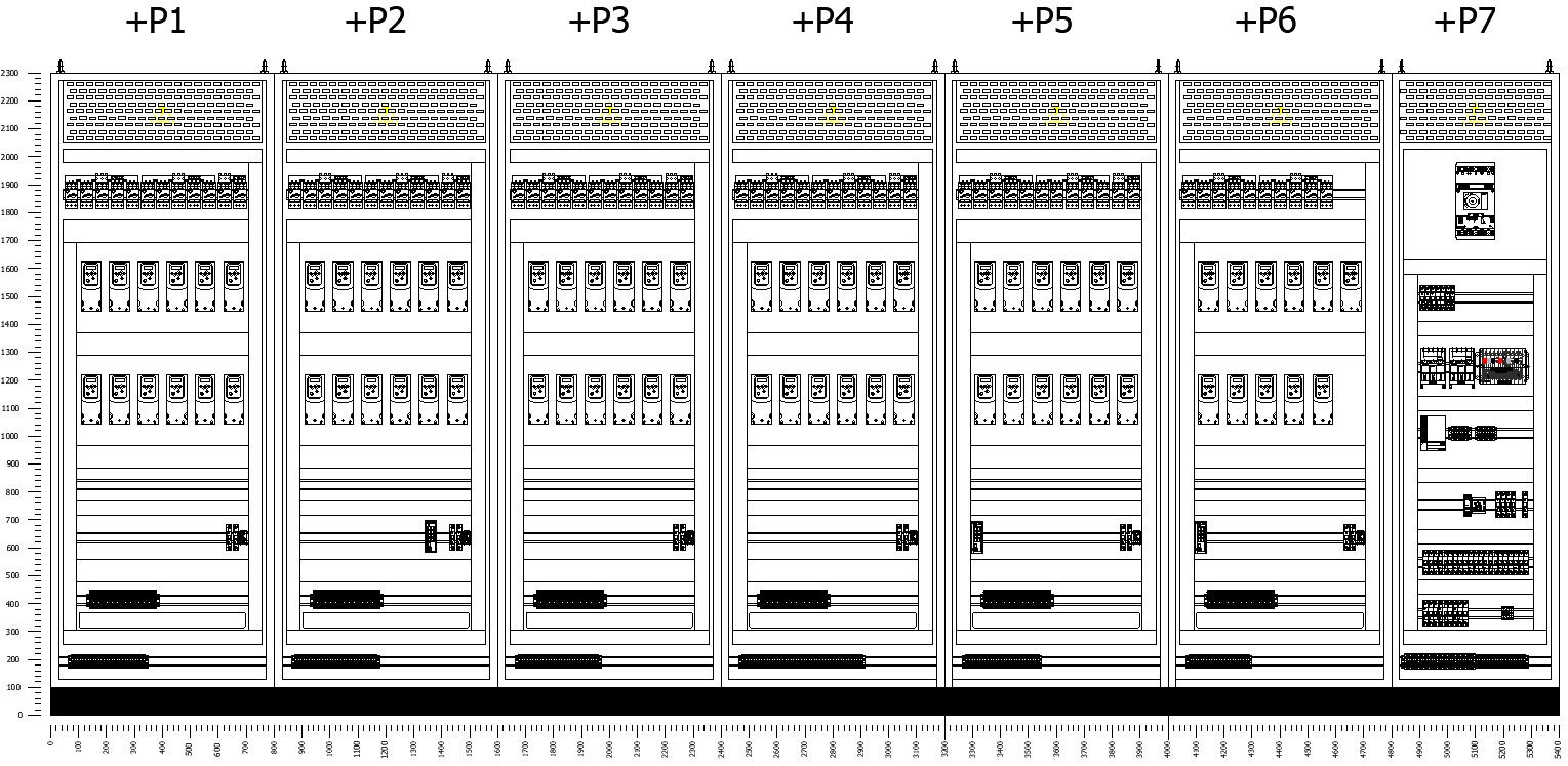
Architectural Front Elevation Panel Design with P1 P7 Sections
Tags
Ratings & Reviews
Be the first to share your experience with this product. Your review helps others make better decisions!
Description
This AutoCAD DWG drawing presents a detailed front elevation control panel layout showing multiple panel sections labeled +P1, +P2, +P3, +P4, +P5, +P6, and +P7. The drawing illustrates a full-height panel arrangement with clear vertical and horizontal measurements, ensuring accurate alignment and spacing across all sections. Each panel includes organized component placement such as breakers, meters, switches, terminal blocks, and mounting rails, represented in precise front elevation view. The overall layout supports structured electrical planning by clearly defining panel widths, heights, and component zones within an industrial or building services setup.
The front elevation plan is suitable for electrical room layouts, control panel documentation, and technical coordination drawings used in commercial and industrial projects. The DWG file allows easy modification and scaling for different project requirements while maintaining drafting accuracy. It is compatible with AutoCAD, Revit, 3D Max, and SketchUp workflows, making it useful for architects, civil engineers, electrical planners, interior designers, and builders. By downloading this drawing through a Cadbull subscription, users gain access to a professional control panel elevation resource that improves design clarity, supports precise installation planning, and reduces repetitive drafting effort in detailed project documentation.




Uploaded by:
viddhi chajjed
Tags
Ratings & Reviews
Be the first to share your experience with this product. Your review helps others make better decisions!