Single Line Grounding Diagram With Antenna System Details Plan
Ratings & Reviews
Be the first to share your experience with this product. Your review helps others make better decisions!
Description
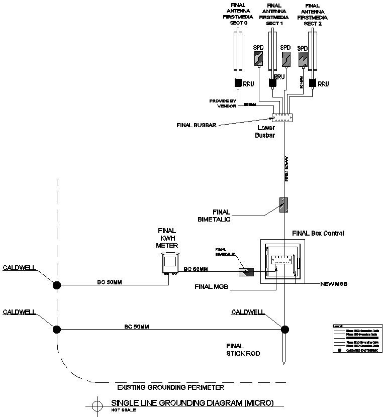
This single-line grounding diagram provides a detailed electrical grounding system layout for an antenna installation project. The drawing illustrates three antenna sectors connected through RRU units, surge protection devices, final busbar connections, and grounding components designed for effective electrical protection. Important elements such as the KWH meter, final MGB, final bimetallic connections, lower busbar, final box control, and new MGB are clearly represented. The layout also includes BC 50MM grounding cable routes and interconnections between grounding points to ensure proper system continuity and performance. This electrical grounding plan serves as a technical reference for grounding network coordination and installation documentation.
The drawing further presents grounding perimeter details with Caldwell grounding points, final stick rod placement, grounding cable alignment, and equipment bonding arrangements. Electrical engineers and design professionals can use this single-line grounding diagram to understand grounding pathways, equipment protection methods, surge control integration, and grounding distribution across the antenna system. The plan offers clear documentation of electrical safety infrastructure, grounding connections, control box arrangements, and network grounding requirements. All components are accurately detailed to support electrical planning, construction documentation, installation review, and technical coordination using AutoCAD files and CAD-based design workflows.
File Type:
DWG
File Size:
2.7 MB
Category::
Electrical
Sub Category::
Electrical Automation Systems
type:
Gold
Tags
Uploaded by:
viddhi
chajjed
Ratings & Reviews
Be the first to share your experience with this product. Your review helps others make better decisions!