MIC Multi Plate AutoCAD 2D Drawing with 120x120x4mm Plate Details
Tags
Ratings & Reviews
Be the first to share your experience with this product. Your review helps others make better decisions!
Description
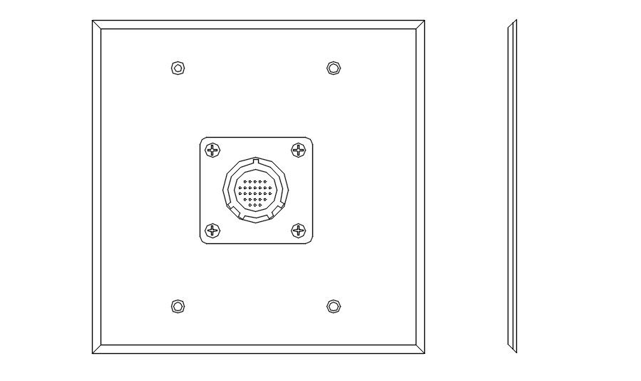
This AutoCAD 2D drawing presents a detailed MIC multiplate design prepared for technical and equipment layout drawings. The drawing clearly illustrates a square multiplate with precise dimensions of 120 x 120 x 4 mm, including fixing holes, plate edges, and a centrally positioned multi-connector unit. The design also shows an eight-channel connector layout with accurate alignment and proportional detailing, making it suitable for electrical, communication, and low-voltage system planning. The MIC multi plate AutoCAD drawing, multi plate CAD detail, AutoCAD connector plate drawing, MIC connector block CAD, multi-channel plate AutoCAD, and 2D equipment plate drawing are clearly represented for professional drafting use.
The plate design follows standard fabrication and installation requirements, with consistent plate thickness, evenly spaced fixing points, and clearly defined connector geometry for reliable mounting. The side view detail supports understanding of plate thickness and edge profile for manufacturing reference. This AutoCAD-compatible DWG file allows easy scaling, layer control, and precise editing within working drawings. Architects, civil engineers, interior designers, and CAD professionals can use the MIC multi plate AutoCAD drawing, multi plate CAD detail, AutoCAD connector plate drawing, MIC connector block CAD, multi channel plate AutoCAD, and 2D equipment plate drawing to ensure accuracy and efficiency in technical documentation through a professional subscription download.
Uploaded by:
viddhi chajjed
Tags
Ratings & Reviews
Be the first to share your experience with this product. Your review helps others make better decisions!