Electrical Manhole Section AutoCAD Drawing with Dimensions and Cover
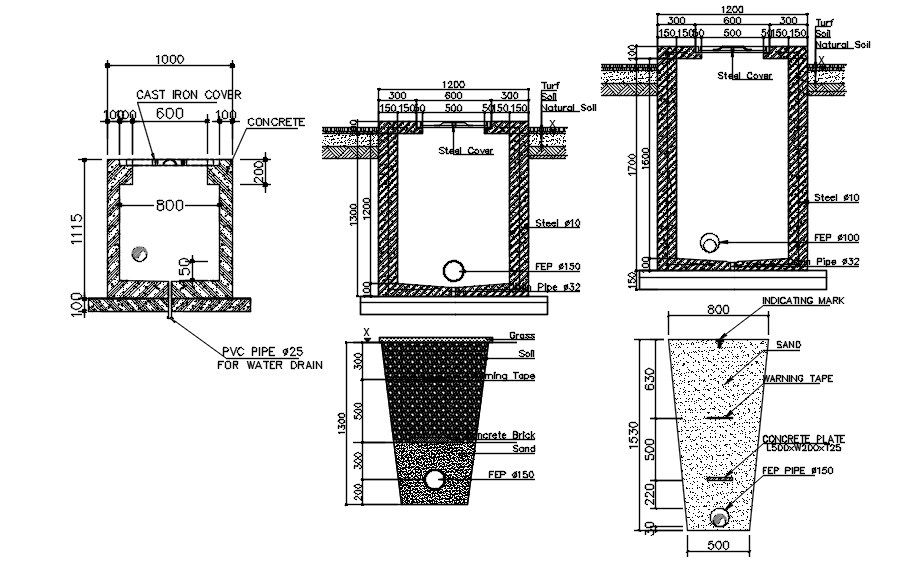
Description
This Electrical Manhole Section AutoCAD drawing presents a clear and technically accurate 2D sectional representation of underground electrical manhole construction. The drawing shows multiple manhole section variations with detailed dimensions, including internal clear widths of 800 mm, overall depths ranging from approximately 1115 mm to 1700 mm, and cover slab widths up to 1200 mm. Construction elements such as a 600 mm cast iron cover, steel cover options, reinforced concrete walls, base slab thickness, and surrounding natural soil layers are clearly identified. Drainage provisions, including a 25 mm PVC pipe and 150 mm FEP pipes, are shown to support effective water management. Additional elements like warning tape, sand bedding, grass or turf finish, and concrete brick infill are illustrated to support construction-level understanding.
This Electrical Manhole AutoCAD drawing is suitable for architects, civil engineers, interior designers, builders, and utility planners involved in electrical and infrastructure projects. The drawing supports underground service coordination, depth control, structural detailing, and maintenance access planning. Prepared as an AutoCAD DWG file, it integrates smoothly with AutoCAD, Revit, SketchUp, and 3D Max workflows for further detailing and coordination. Clear annotations, sectional clarity, and dimensioned layouts make this drawing a reliable reference for electrical manhole construction and professional documentation.
File Type:
DWG
File Size:
1.1 MB
Category::
Electrical
Sub Category::
Electrical Automation Systems
type:
Gold
Uploaded by:
viddhi
chajjed
