Buffer Hopper System 2D Layout with Weighing and Bag Station Flow
Tags
Ratings & Reviews
Be the first to share your experience with this product. Your review helps others make better decisions!
Description
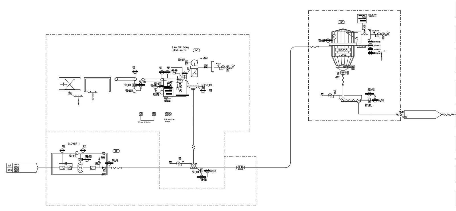
This buffer hopper system drawing is a detailed AutoCAD 2D layout prepared for industrial material handling and process coordination. The drawing clearly illustrates the buffer hopper container positioned between the upper big bag station and the downstream processing line, acting as a controlled holding unit. The system layout shows material flow paths, inlet and outlet connections, valve positions, and interface points with weighing or level probe devices used for monitoring material quantity. Equipment blocks, dashed system boundaries, and connection lines help define operational zones and functional sequencing within the buffer hopper system. This buffer hopper system 2d drawing supports an accurate understanding of how materials are temporarily stored, measured, and transferred during production processes.
The buffer hopper system 2d drawing is drafted with clean linework, readable symbols, and proportional spacing suitable for professional documentation. Architects and civil engineers can use this drawing to study equipment coordination, piping alignment, and system integration within industrial plants. Builders and designers benefit from clear visualization of hopper placement, connection routing, and operational flow logic. Compatible with AutoCAD, Revit, SketchUp, and 3d Max workflows, this drawing becomes a valuable subscription resource for industrial process layout planning and technical drawing libraries.
Uploaded by:
viddhi chajjed
Tags
Ratings & Reviews
Be the first to share your experience with this product. Your review helps others make better decisions!