2D Anchor Bolt Detail Design with 240mm Plate and 370mm Base
Description
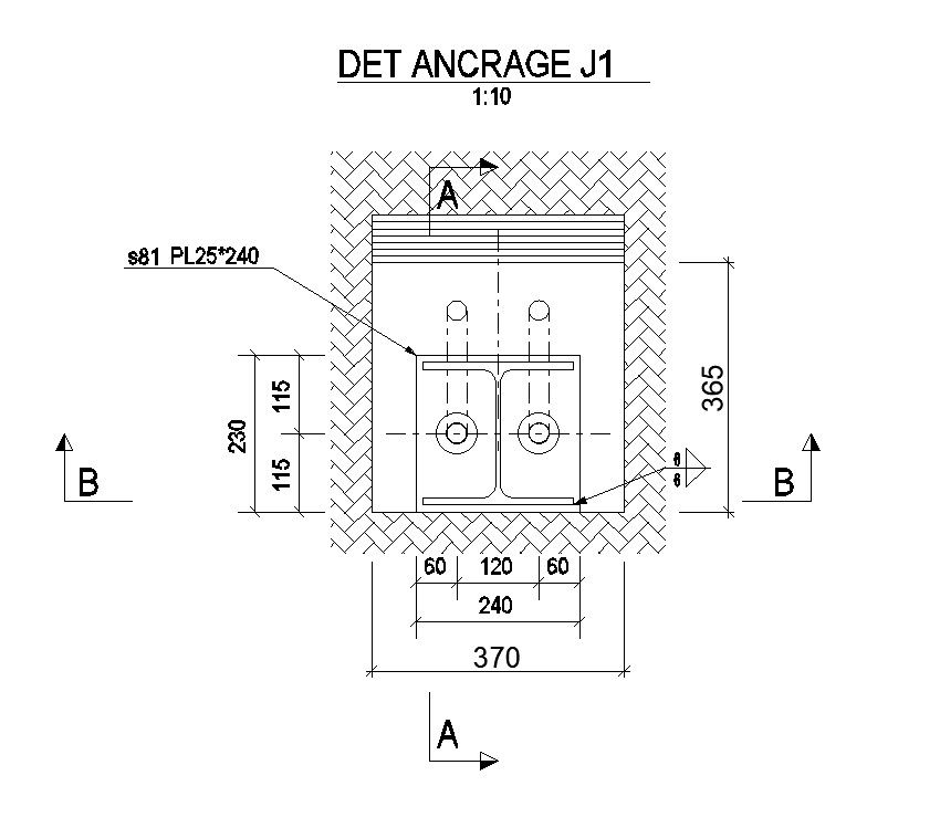
This 2D anchor bolt detail design is a precise AutoCAD drawing prepared for structural steel to concrete connection detailing. The drawing clearly illustrates the anchor bolt arrangement used to fasten structural components securely into concrete foundations. It includes a detailed anchorage layout with a base width of 370mm and a central plate dimension of 240mm, supported by symmetric spacing of 60mm on both sides. Vertical dimensions of 365mm and internal spacing of 115mm plus 115mm are clearly shown to explain embedment depth and bolt positioning. The drawing also identifies plate specification PL 25 x 240 and section references marked as A A and B B, helping engineers understand anchorage alignment and sectional behavior. This anchor bolt detail drawing supports accurate interpretation of load transfer between steel structures and concrete foundations.
The anchor bolt 2d drawing is drafted at a clear scale of 1:10, ensuring dimensional accuracy and construction level clarity. Architects and civil engineers can use this anchor bolt autocad file to study threaded bolt connections embedded into concrete and connected to steel supports. The drawing integrates smoothly with AutoCAD Revit SketchUp and 3d Max workflows. With clearly marked dimensions bolt spacing and plate sizes, this anchor bolt detail design becomes a valuable subscription resource for structural detailing and foundation connection documentation.
File Type:
DWG
File Size:
2 MB
Category::
Mechanical and Machinery
Sub Category::
Factory Machinery
type:
Gold
Uploaded by:
viddhi
chajjed
