Boundary Wall Section Elevation Design With 4.99m Layout Details
Ratings & Reviews
Be the first to share your experience with this product. Your review helps others make better decisions!
Description
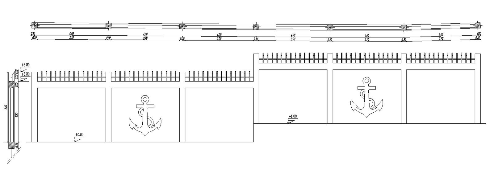
This boundary wall section elevation design drawing presents detailed architectural layout information with structured wall components and dimensional references suitable for planning and drafting applications. The AutoCAD files include boundary wall elevation details, sectional representations, panel divisions, decorative wall elements, and construction alignment information. The drawing shows repeated wall sections with decorative anchor symbols and vertical railing arrangements across the upper portion of the structure. Dimensional references visible in the layout include panel measurements of approximately 4.99m, 4.00m, and additional sectional spacing details that assist in understanding proportional construction arrangements and design continuity. The boundary wall design provides practical references for architectural development and site enclosure planning.
The boundary wall section elevation layout also includes level references, wall height indications, structural spacing, and organized drafting elements that support accurate project visualization. The AutoCAD files help architects, civil engineers, builders, and interior planning professionals understand wall geometry, elevation presentation, and sectional detailing for residential and commercial projects. The drawing can be used for boundary planning, architectural drafting, wall construction studies, and design documentation where precise layout representation and measured design information are required for project execution and technical planning purposes.
Tags
Uploaded by:
viddhi
chajjed
Ratings & Reviews
Be the first to share your experience with this product. Your review helps others make better decisions!