Typical Beam Section Details AutoCAD Drawing With 40x40 to 40x80
Tags
Ratings & Reviews
Be the first to share your experience with this product. Your review helps others make better decisions!
Description
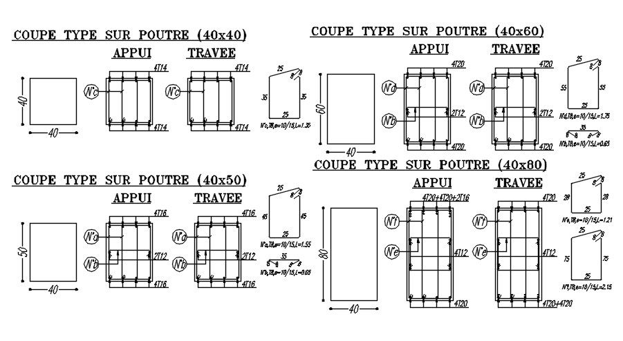
This AutoCAD 2D drawing illustrates typical reinforced concrete beam section designs with clearly defined dimensions and reinforcement detailing. The drawing includes multiple beam sizes, such as 40x40, 40x50, 40x60, and 40x80, presented with separate support and span conditions. Each section shows stirrup spacing, longitudinal bar placement, concrete cover, and cross-sectional geometry with accurate dimensional annotations. The comparison of beam sizes helps users understand structural variation, load behaviour, and detailing differences between smaller and larger beam sections. Clear labelling and consistent drafting make the drawing suitable for reading, checking, and coordination during structural design stages.
The DWG file supports structural planning, construction detailing, and technical documentation for residential, commercial, and institutional building projects. The drawing focuses only on beam section configuration, reinforcement layout, and measurement accuracy, making it useful for architects, civil engineers, and construction professionals. The 2D format allows easy reference, modification, and coordination with slab, column, and foundation drawings. This AutoCAD beam section drawing provides reliable visual guidance for understanding standard beam dimensions, reinforcement logic, and section detailing used in reinforced concrete structures.
Uploaded by:
viddhi chajjed
Tags
Ratings & Reviews
Be the first to share your experience with this product. Your review helps others make better decisions!