Electrical Substation Detailed Layout Plan with Cable Duct Design
Ratings & Reviews
Be the first to share your experience with this product. Your review helps others make better decisions!
Description
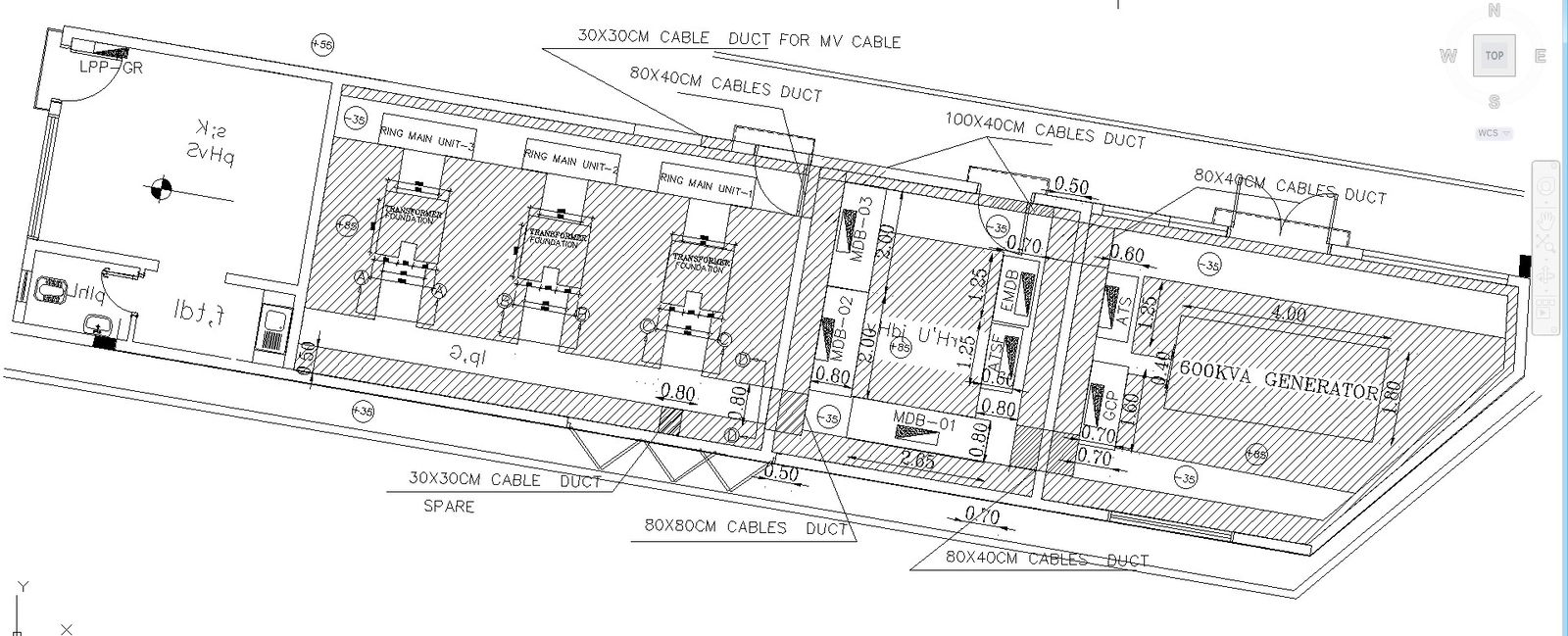
This AutoCAD DWG drawing presents a detailed electrical substation layout plan with clearly defined equipment zones and cable duct routing. The plan illustrates transformer foundations, ring main units, main distribution boards, and generator placement arranged in a linear substation configuration. Cable ducts of varying sizes, such as 30×30 cm, 80×40 cm, 80×80 cm, and 100×40 cm, are clearly marked to support MV and LV cable routing. Walkway widths, equipment clearances, and access paths are dimensioned accurately to ensure safe operation and maintenance planning within the substation area.
The drawing also highlights generator space allocation, MDB positioning, earthing references, and interconnections between electrical components. Structural boundaries, internal partitions, and service corridors are clearly shown for coordination between civil and electrical works. Dimension annotations help users understand spacing between equipment, duct alignment, and overall site utilization. This DWG file is suitable for electrical engineers, civil engineers, planners, consultants, and students involved in substation design and execution. It provides a reliable AutoCAD reference for electrical substation planning, cable management coordination, and infrastructure layout using professional CAD drafting standards.
Tags
Uploaded by:
K.H.J
Jani
Ratings & Reviews
Be the first to share your experience with this product. Your review helps others make better decisions!