Electrical Substation Layout Plan with Equipment Arrangement Drawing
Tags
Ratings & Reviews
Be the first to share your experience with this product. Your review helps others make better decisions!
Description
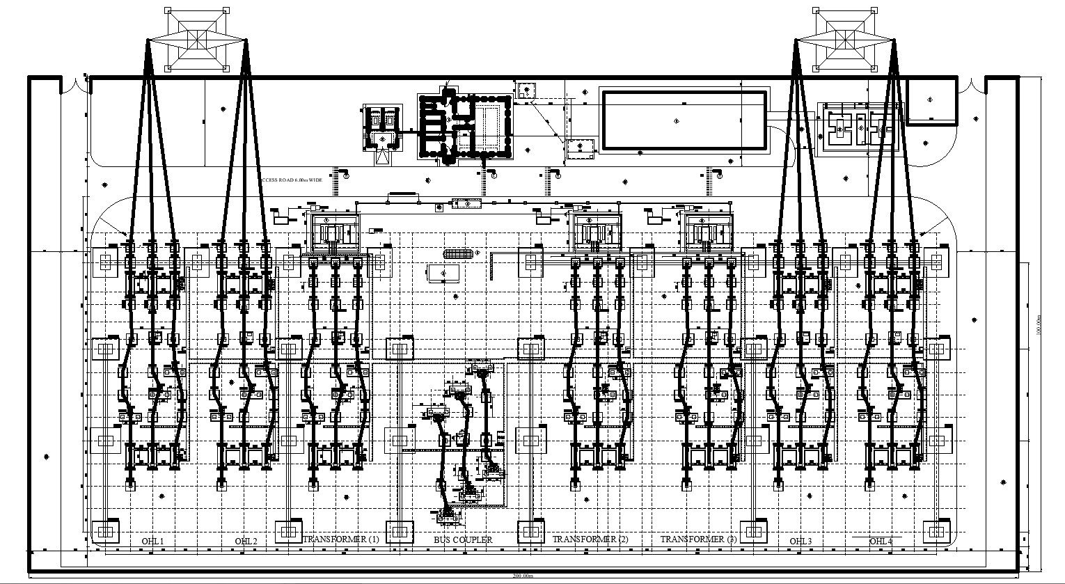
This AutoCAD DWG drawing presents a detailed electrical substation layout plan with clearly defined equipment arrangement and circulation zones. The plan illustrates transformer locations, bus coupler alignment, outgoing and incoming feeder bays, and equipment spacing within the substation yard. Structural grids, equipment foundations, and cable routing paths are accurately represented to support proper installation and operational safety. Access roads, service clearances, and equipment zones are clearly marked, helping users understand functional movement and maintenance planning within the substation layout.
The drawing also shows organized placement of electrical components such as transformers, bus bars, switchgear zones, and control areas, ensuring efficient power distribution and coordination. Dimension annotations define equipment spacing, boundary limits, and internal clearances required for safe operation. The layout supports coordination between civil and electrical design elements, making it suitable for construction and planning reference. This DWG file is ideal for electrical engineers, civil engineers, planners, consultants, and students involved in substation design projects. It provides a reliable AutoCAD reference for understanding substation equipment layout, spatial planning, and infrastructure coordination using professional CAD drafting standards.

Uploaded by:
K.H.J Jani
Tags
Ratings & Reviews
Be the first to share your experience with this product. Your review helps others make better decisions!