Electrical Substation Foundation Layout Plan with Footing Details
Tags
Ratings & Reviews
Be the first to share your experience with this product. Your review helps others make better decisions!
Description
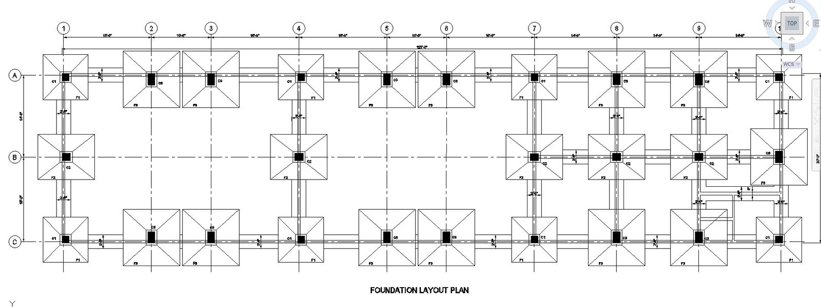
This AutoCAD DWG drawing presents a detailed foundation layout plan for an electrical substation, clearly showing footing positions, column locations, and structural grid alignment. The plan illustrates the systematic arrangement of isolated footings connected through foundation beams, ensuring proper load distribution for substation equipment and structures. Grid lines, reference axes, and spacing dimensions are accurately marked to help users understand the overall foundation geometry and site coordination. Each footing is labeled with identification tags, making the drawing suitable for construction planning and verification.
The foundation plan also highlights reinforcement zones, pedestal locations, and connection paths between foundations, supporting stability and structural integrity. Clear dimensioning along both horizontal and vertical directions allows precise setting out on site. The drawing is suitable for understanding foundation depth, spacing between footings, and alignment with superstructure elements. This DWG file is ideal for civil engineers, electrical engineers, planners, contractors, and students involved in substation construction projects. It serves as a reliable AutoCAD reference for foundation execution, coordination, and documentation, ensuring accuracy and efficiency in electrical substation infrastructure development.
Uploaded by:
K.H.J Jani
Tags
Ratings & Reviews
Be the first to share your experience with this product. Your review helps others make better decisions!