Water Treatment Plant Plumbing Pipe Layout CAD Design Drawings
Tags
Ratings & Reviews
Be the first to share your experience with this product. Your review helps others make better decisions!
Description
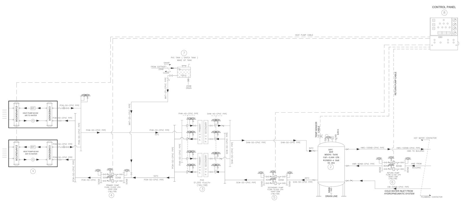
This AutoCAD DWG file presents a detailed plumbing pipe layout design for a water treatment plant, prepared with clear plans and schematic representations. The drawing illustrates raw water inlet lines, treated water supply lines, return piping, pump connections, storage tank interfaces, and control panel routing. Pipe sizes, flow directions, valve locations, heat pump connections, and mixing tank arrangements are clearly indicated to support accurate system understanding. The layout uses standard plumbing symbols and consistent linework, making it suitable for technical coordination, system planning, and service integration. This drawing helps visualize how different plumbing components connect within a water treatment process for domestic and utility water usage.
This plumbing pipe layout CAD drawing is suitable for plumbing engineers, MEP consultants, civil engineers, architects, and contractors involved in water treatment plant projects. The AutoCAD format allows easy scaling, editing, and direct integration into construction drawings and coordination documents. Sectional routing and equipment connections support efficient installation planning and maintenance reference. Available through a subscription, this DWG file helps reduce design time while maintaining accuracy and compliance in plumbing system documentation. It is compatible with AutoCAD and can be referenced alongside other design and coordination software used in infrastructure and building services projects.
Uploaded by:
Jiya
Tags
Ratings & Reviews
Be the first to share your experience with this product. Your review helps others make better decisions!