AutoCAD Hot Water Mixing Tank Plant Room Layout With Heat Pumps
Description
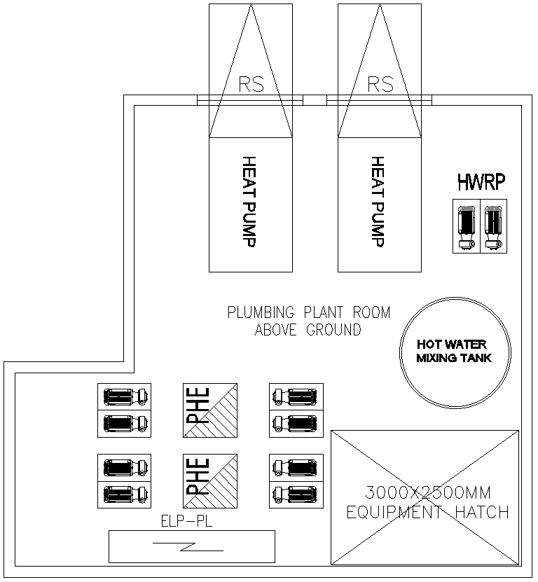
This AutoCAD drawing illustrates a detailed hot water mixing tank layout prepared within an above-ground plumbing plant room. The drawing clearly shows the arrangement of key mechanical components, including two heat pump units with RS connections, a dedicated hot water mixing tank, and HWRP pump assemblies. Plate heat exchangers marked as PHE are positioned with associated pump sets on both sides, ensuring balanced flow distribution. An equipment hatch sized 3000 × 2500 mm is accurately shown to support installation, maintenance, and equipment replacement planning. The layout is clearly labeled, making it suitable for coordination between plumbing and mechanical services.
The DWG file further highlights organized circulation space within the plant room, enabling safe access around heat pumps, pumps, and tanks. The clear zoning of equipment supports efficient piping routing and system maintenance. This drawing is suitable for plumbing engineers, MEP consultants, architects, and contractors involved in hot water generation and distribution systems for residential, commercial, and institutional projects. Available through a subscription, this AutoCAD DWG file helps reduce coordination errors, supports accurate service planning, and ensures efficient placement of hot water mixing equipment in plant room layouts
File Type:
DWG
File Size:
726 KB
Category::
Electrical
Sub Category::
Architecture Electrical Plans
type:
Free

Uploaded by:
Eiz
Luna