Typical Confinement Column Section Construction Drawing With Details
Description
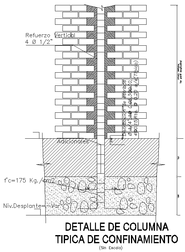
This AutoCAD drawing presents a detailed typical confinement column section used in masonry and reinforced concrete construction. The section clearly illustrates vertical reinforcement consisting of 4 bars of 12 mm diameter, centrally placed within the column core. Brick masonry arrangement on both sides of the column is shown with proper bonding and confinement zones. The drawing includes precise annotation of concrete grade with f’c value around 175 kg per square centimeter, footing integration, and load transfer path from column to foundation. Plaster thickness, concrete cover, and reinforcement alignment are accurately detailed to support structural clarity and execution accuracy.
The lower portion of the drawing highlights foundation construction with rubble soling, PCC bedding, and footing block dimensions. Level references, such as plinth level and foundation depth, are clearly marked for site coordination. Masonry interfaces, column anchorage, and confinement detailing are presented in a clean sectional format suitable for structural documentation. This DWG file is ideal for civil engineers and structural designers working on residential and low-rise building projects. Subscription access enables professionals to directly use this ready-made AutoCAD drawing to improve drafting efficiency, ensure dimensional accuracy, and maintain compliance with standard construction detailing practices.

Uploaded by:
Eiz
Luna