Urban Water Channel Section Drawing For Treatment Plant With Dimension
Description
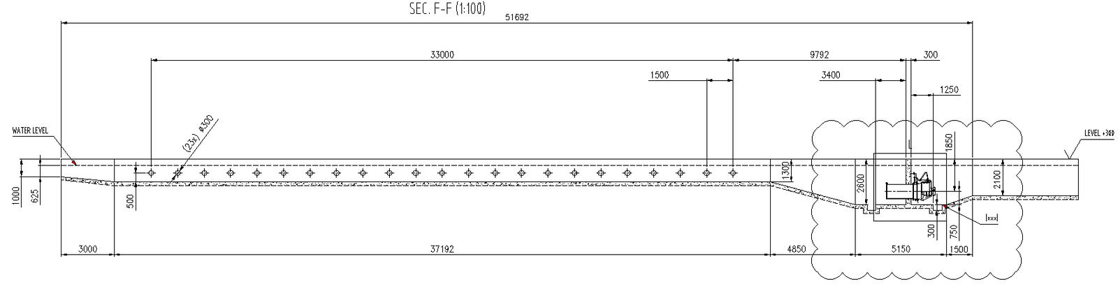
This AutoCAD drawing presents a detailed urban water channel section designed for water treatment plant infrastructure. The section drawing clearly illustrates the longitudinal profile with precise dimensional data, including an overall section length of approximately 51692 mm, internal channel length of 33000 mm, and transition zones measuring 9792 mm and 300 mm. The drawing shows defined water level markers, channel bed slope, concrete lining thickness, and base depth ranging around 500 mm to 1000 mm. Side wall heights, stepped level changes, and gradual slope connections are accurately indicated to support hydraulic flow and structural stability.
The DWG file also includes detailed construction zones for mechanical or control chamber integration, with chamber widths around 5150 mm and depth references of 2100 mm and 2600 mm. Platform offsets, clearance distances, and access provisions are clearly dimensioned for coordination with treatment plant equipment. This section drawing is suitable for civil engineers and urban designers involved in wastewater treatment, drainage systems, and infrastructure planning. Subscription access enables professionals to directly use this technically accurate CAD file to reduce drafting time, improve coordination accuracy, and ensure reliable construction documentation.
File Type:
DWG
File Size:
1.3 MB
Category::
Urban Design
Sub Category::
Town Water Treatment Design
type:
Gold

Uploaded by:
Eiz
Luna