Central Caisson Cross Section Drawing With Ø100 Pipe And Levels
Tags
Ratings & Reviews
Be the first to share your experience with this product. Your review helps others make better decisions!
Description
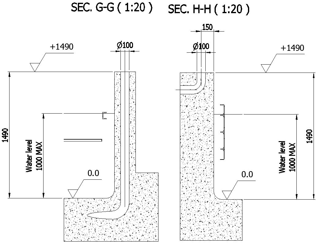
This AutoCAD drawing illustrates a detailed central caisson cross-section prepared for a small-scale structural model. The drawing includes two sectional views marked as Section G G and Section H H at a scale of 1:20, providing a clear visualization of internal geometry and concrete profiling. A vertical Ø100 mm pipe is shown passing through the caisson body with defined bends and offsets, ensuring accurate representation of service routing. Finished level references are clearly marked at +1490 mm, while the base reference level is indicated at 0.0 for construction alignment. The maximum water level is defined at 1000 mm, supporting hydraulic and drainage analysis within the caisson structure.
The caisson body is represented with solid concrete hatching, stepped base geometry, and embedded pipe detailing to reflect realistic construction conditions. Dimensional callouts such as 150 mm horizontal offset and full vertical height of 1490 mm ensure clarity for fabrication and site execution. Section lines, level markers, and material representation help engineers and designers understand load transfer and water containment behavior. This AutoCAD DWG file is suitable for civil engineering, foundation planning, and hydraulic structure detailing. Access through a subscription allows professionals to integrate this precise central caisson cross-section drawing into AutoCAD, Revit, and other compatible CAD platforms for accurate technical documentation.

Uploaded by:
Eiz Luna
Tags
Ratings & Reviews
Be the first to share your experience with this product. Your review helps others make better decisions!