Nozzle Orientation Plan Elevation Section Detail For Machinery Design
Tags
Ratings & Reviews
Be the first to share your experience with this product. Your review helps others make better decisions!
Description
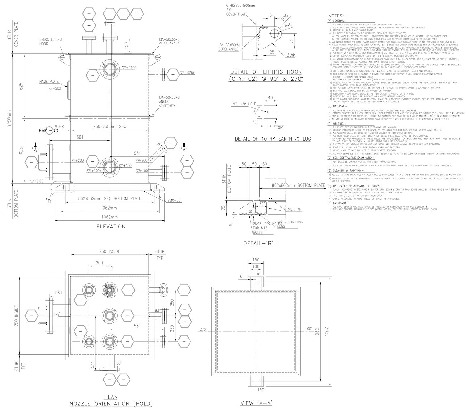
This AutoCAD DWG file presents a complete nozzle orientation detail with clearly defined plan, elevation, and sectional views for machinery and equipment layouts. The drawing includes a 750 x 750 mm square body with a 6 mm thick cover plate and bottom plate, supported on an 862 x 862 mm square bottom plate. Overall base width is shown as 1062 mm with precise centerline references and elevation levels such as +0, +100, +200, +900, and +1100. Nozzle orientations are accurately placed at 0°, 90°, 180°, and 270° positions, ensuring correct alignment for piping connections. ISA 50 x 50 x 6 curb angles and stiffeners are detailed for structural rigidity.
The DWG also includes detailed drawings of lifting hooks at 90° and 270° positions, 10 mm thick earthing lugs, and anchoring details with 2 numbers of 22 mm holes for M16 bolts. Plate thicknesses such as 6 mm and 12 mm are clearly noted, along with nozzle projection dimensions and center offsets. Section A and Detail B views provide clarity for fabrication, erection, and inspection. This drawing is suitable for mechanical engineers, plant designers, and fabrication teams who require precise dimensional data for the manufacturing and installation of machinery nozzle arrangements.

Uploaded by:
Eiz Luna
Tags
Ratings & Reviews
Be the first to share your experience with this product. Your review helps others make better decisions!