Condensing Unit Installation Plan And Section With Pipe Support
Tags
Ratings & Reviews
Be the first to share your experience with this product. Your review helps others make better decisions!
Description
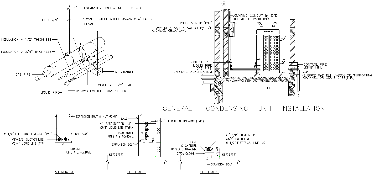
This AutoCAD DWG drawing provides a detailed plan and section view for general condensing unit installation used in HVAC and refrigeration systems. The drawing clearly illustrates the placement of the condensing unit on a structural base with a rubber pad support across the full width of the channel for vibration control. Refrigerant piping layouts include suction lines of 1 to 3 8-inch diameter and liquid lines of 3 4-inch diameter, along with control pipes and electrical conduit routing. Pipe insulation thicknesses of 1 2 inch and 3 4 inch are accurately shown, ensuring thermal efficiency and condensation control. Support details include C channel unistrut sizes of 40x40 mm and 75x40 mm fixed with 3 8-inch expansion bolts and threaded rods.
The section details also highlight clamp arrangements, galvanized steel sheet clamps, conduit sizes of 1 2 inch EMT or IMC, and clear separation between gas pipes, liquid pipes, and electrical lines. Dimensional references such as vertical offsets of around 292 mm and 500 mm are provided for accurate alignment. Safety switch mounting, wall penetration details, and purge connections are clearly labeled. This AutoCAD DWG file is suitable for HVAC engineers, MEP consultants, architects, and contractors who require precise condensing unit installation drawings with measurements, pipe support details, and coordination clarity for efficient system execution.

Uploaded by:
Eiz Luna
Tags
Ratings & Reviews
Be the first to share your experience with this product. Your review helps others make better decisions!